5
3
MECHANICAL INSTALLATION…
3.1.2
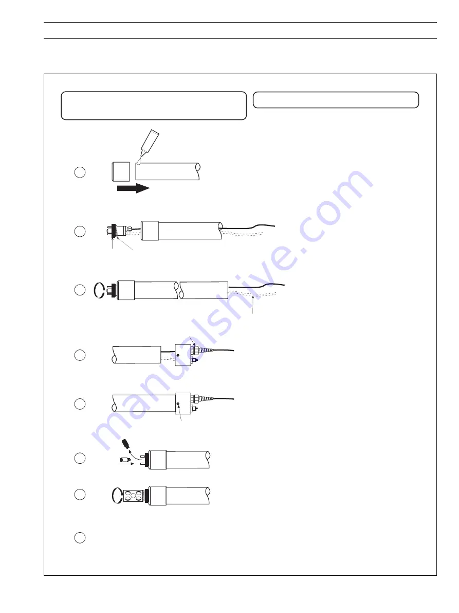
Dip – Fig. 3.2
For installation of the assembled unit see Section 3.2.2 Dip Systems.
Fig. 3.2 Dip Kit Assembly
Clean mating surfaces thoroughly. Then with the solvent
cement provided, and to the instructions given on the
tube, cement the adaptor to the pipe.
Allow the solvent cement to set for 24 hours before
proceeding.
Secure the end cap to the pipe with the self tap screw.
Tighten the cable gland.
Information. Pipe requirement (user supplied):
O.D. 1.9", 1
1
/
2
" N.B., pressure rating 10 bar+, and cut length
to suit.
1
5
2
Ensure that the gasket is in place on the
sensor block. Feed the cable attached
to the sensor block (and water wash
tube if fitted) through the adaptor and
pipe.
Adaptor
Pipe
Sensor
Block
Screw the sensor block into the
adaptor firmly and cut the water wash
tube, if fitted, allowing sufficient to fit
to the connector in the end cap and
a little slack for manoervering.
Gasket
Cut
Feed the cable through the cable gland in the end cap.
Push the water wash tube (if fitted) onto the connector
in the end cap and secure with a hose clamp.
3
4
Self Tap Screw
Cable Gland
Remove the dummy sensor capsule and fit the dissolved
oxygen sensor capsule. A suitable procedure (and
cautions) is included in Fig. 5.1.
Screw the shroud onto the sensor block.
7
6
Proceed to Section 3.2.2 for installation procedure.
8
Note. There is no bracket supplied with this kit.
Summary of Contents for 9408 750
Page 1: ...Dissolved Oxygen Systems 9408 Series Instruction Manual IM 9408_7...
Page 17: ...15 NOTES...
Page 18: ...16 NOTES...


