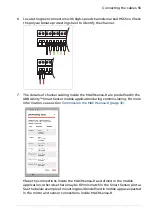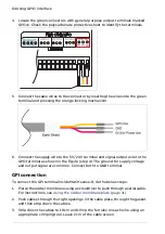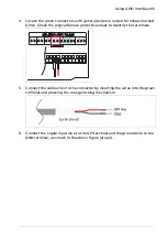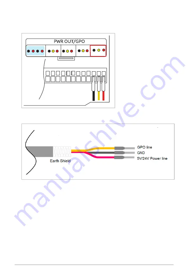
4. Locate the green connectors with general purpose output terminals marked
GPOxx. Check the polycarbonate protective sheet to identify the terminals.
PWR OUT/GPO
GPO00
GND GPO 24V
5V
PWR OUT*
GND SV GND 24V
GPO01
GPO02
GPO03
5. Connect the cable wires to the connector by inserting the wires into the green
terminal and pressing the orange locking mechanism.
6. Connect the supply wire to the 5 V/24 V terminal and signal output wire to the
GPO terminal as shown in the figure (step 4). The ground for supply voltage
and output signal are common. Connect both to GND terminal.
GPI connection
To connect the GPI terminal inside MACHsense-R, do the below steps:
1.
Pierce the rubber membrane using a screwdriver to push through a serial cable.
For instructions, see
Using the rubber membrane plate (page 31)
.
2.
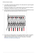
Push cables through the tight openings in the cable plate, through the gasket
and then strip down the cables.
3.
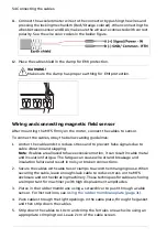
Strip down the cables to 10 cm and crimp the ferrules on each wire using an
appropriate crimping tool. Leave 2 cm of the cable screen.
64 Using GPIO interface
Summary of Contents for Ability MACHsense-R
Page 1: ...ABB MOTION SERVICES ABB Ability MACHsense R MSR1608 Data acquisition unit User manual...
Page 2: ......
Page 4: ......
Page 8: ...8...
Page 12: ...12...
Page 18: ...18...
Page 20: ...Process overview diagram 20 Getting started...
Page 26: ...26...
Page 34: ...34...
Page 42: ...42...
Page 46: ...46...
Page 50: ...50...
Page 58: ...58...
Page 66: ...66...


