Section 3 Fieldbus Topologies
Bus connector
3BDS009029R5001 B
67
Bus connector
A bus connector is used to connect the bus cable to the PROFIBUS device. Bus
connectors are available with a variety of protection classes and mechanical designs.
The choice of connector is mainly determined by the space available in the vicinity
of the PROFIBUS device.
The bus connector must have a low-impedance connection to the cable shield.
A 9-pin D-Sub connector is primarily used to connect PROFIBUS devices on the
bus, which complies with DIN 19245/ EN 50170.
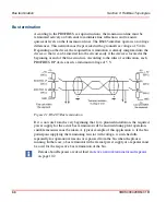
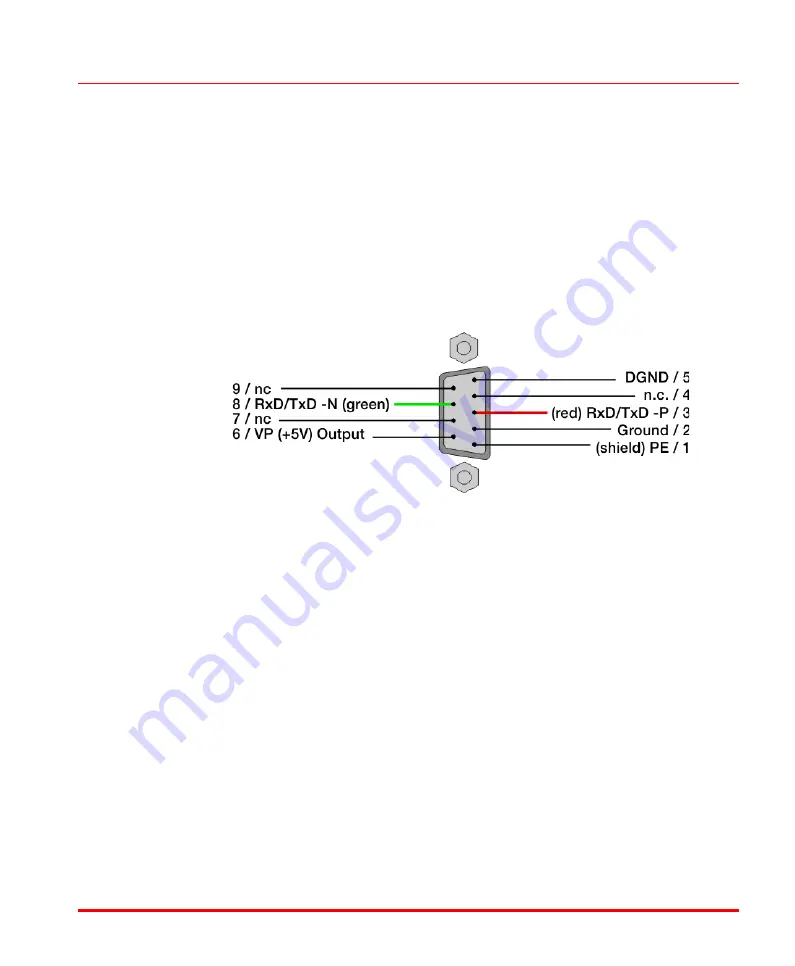
To allow correct bus termination, each station must connect the signals DGND
(Ground) and VP (5 V) to pins 5 and 6 of the connector, respectively. The 5 V
supply for the terminating resistors (VP) should have a minimum current rating of
10 mA (the current load can increase to 12 mA if a NULL signal is sent through the
bus).The current rating should be increased to approximately. 90 mA if you need to
be able to supply other types of devices on the bus such as bus terminator and
optical fiber cable drivers.
The
RxD/TxD-P
signal wire connected to pin 3 of the PROFIBUS module
connector must be connected to the relevant signal wires with the same designation
of all nodes. Proceed accordingly with the
RxD/TxD-N
signal lines on pin 8 of the
connector.
All fieldbus devices which use a standard 9-pin Sub-D connector should provide the
the VP and DGND signals on the bus connector in addition to the receive and
Figure 22. Electrical port - assignment of Sub-D sockets
Summary of Contents for AC 800M
Page 2: ......
Page 3: ...AC 800M PROFIBUS DP Installation System Version 5 0 5 1...
Page 8: ...Table of Contents 8 3BDS009029R5001 B...
Page 16: ...Released User Manuals and Release Notes About This User Manual 16 3BDS009029R5001 B...
Page 116: ...Updates in Revision Index B 116 3BDS009029R5001 B...
Page 117: ......


