Installing the PM8xx/TP830 Processor Unit in Single Configuration
Section 2 Installation
56
3BSE 027 941 R301
Installing the PM8xx/TP830 Processor Unit in Single
Configuration
Use the procedure below to install the processor unit along the DIN-rail:
1.
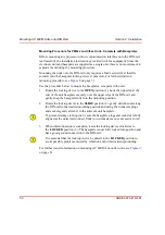
If already mounted, remove the CEX-bus and ModuleBus terminations from
the sides of the processor unit.
2.
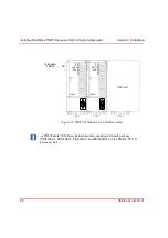
Mount the processor unit, the communication interfaces and the S800 I/O units
(the communication interfaces on the CEX-bus to the left of the processor unit
and the S800 I/O units on the electrical ModuleBus to the right of the processor
unit).
3.
Press them gently together and make sure that the ModuleBus and the CEX-
bus are correctly connected, via baseplate connectors.
4.
Reinsert the bus terminations into the communication units at farthest away
from the processor unit.
a.
For CEX-bus TB850 (TB851 if cable TK850 is used), see
on page 59. If no units are used on the CEX-bus, no
bus termination is required.
b.
For ModuleBus TB807, refer to the S800 I/O documentation (see
on page 17). If no units are used on the ModuleBus, no
bus termination is required.
5.
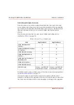
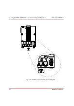
TP830 Baseplate cable connections:
a.
Connect the power leads and, if applicable, power supervision signals
from SS822 to screw terminals SA and SB (see
b.
Connect the Control Network cables to CN1 (single connection) or CN1 +
CN2 (redundant connection).
c.
Connect the serial protocol to COM3.
For PM861/PM864 insert the RCU Link Termination plug TB852, at the RCU
Link connector. The termination plug must always be used for PM861/PM864
when running in single configuration.
When a redundant processor is running in a single configuration use the RCU
Link Cable TK851, if the RCU Link Termination plug TB852 is not available.
Summary of Contents for AC 800M
Page 1: ...ControlIT AC 800M Version 2 1 Controller Hardware Hardware and Operation...
Page 2: ......
Page 3: ...Controller Hardware Hardware and Operation ControlIT AC 800M Version 2 1...
Page 10: ...7DEOH RI RQWHQWV 10 3BSE 027 941 R301...
Page 20: ...Related Documentation About This Book 20 3BSE 027 941 R301...
Page 26: ...Operating Environment Safety Summary 26 3BSE 027 941 R301...
Page 42: ...Product Release History Section 1 Introduction 42 3BSE 027 941 R301...
Page 108: ...Powering from an External 24 V DC Source Section 3 Configuration 108 3BSE 027 941 R301...
Page 118: ...Verification of Redundant CPU Section 4 Operation 118 3BSE 027 941 R301...
Page 212: ...Low Voltage Directive LVD Appendix D Directive Considerations 212 3BSE 027 941 R301...
Page 214: ...Hazardous Location Approval Appendix E Standards 214 3BSE 027 941 R301...
Page 228: ...QGH 228 3BSE 027 941 R301...
Page 229: ......


