background image

Section 2  Installation

Installing the PM8xx/TP830 Processor Unit in Single Configuration

3BSE 027 941 R301

57


d.

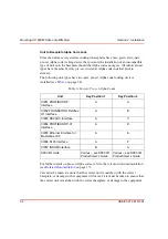
Connect the Control Builder to COM4 with cable TK212 (if required for 
changing an IP address etc). Otherwise connect the Control Builder to the 
Control Network.

6.

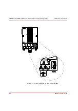
Connect the optical ModuleBus to the optical contacts on the processor unit 
(see

Figure 2

 on page 29 an

Figure 17

 on page 77). Information regarding 

optical cable selection and cable length is provided in the S800 I/O 
documentation (see

Related Documentation

 on page 17).

7.

The PM8xx is supplied with an internal back-up battery. When the battery is to 
be used, place it in the Internal Battery Holder (see

Figure 33

 on page 121). 

When the external SB821 battery unit is to be used, install it according to the 
instructions in 

Installing the SB821 External Battery Unit

 on page 85.

Note that connection to the optical ModuleBus is identical to that for the 
processor unit and for the FCI in S800 I/O (see

Figure 28

 on page 97.)

Do not place the internal back-up battery in the battery holder until the 
AC 800M Controller has been powered-up normally and the memory back-up 
function has been activated. If no normal power supply is connected to the 
processor unit with the battery in place, then the CPU memory will 
immediately start to consume battery power.

Always install a fresh internal or external battery at the end of the installation 
phase. The original battery is heavily utilized due to frequent blackouts during 
system installation.

Summary of Contents for AC 800M

Page 1: ...ControlIT AC 800M Version 2 1 Controller Hardware Hardware and Operation...

Page 2: ......

Page 3: ...Controller Hardware Hardware and Operation ControlIT AC 800M Version 2 1...

Page 4: ...rpose The software or hardware described in this document is furnished under a license and may be used copied or disclosed only in accordance with the terms of such license Copyright 1999 2003 ABB All...

Page 5: ...MPLIANCE 16 UL LISTING 16 Related Documentation 17 Safety Summary General 21 Warnings and Information Symbols in the Text Margin 21 Personnel and Process Safety 22 Machine Safety 24 Before replacing I...

Page 6: ...RS232 C Interface CI853 TP853 71 Installing the PROFIBUS DP V1 Interface CI854 TP854 72 Installing the Ethernet Interface for MasterBus 300 CI855 TP853 74 Installing the S100 I O Interface CI856 TP856...

Page 7: ...112 Automatic Switch Over to Backup CPU 114 Verification of Satisfactory AC 800M Operation 115 Verification of Single CPU 115 Verification of Redundant CPU 117 Section 5 Maintenance Preventive Mainten...

Page 8: ...Interface 153 CI852 and TP852 FOUNDATION Fieldbus H1 Interface 157 CI853 and TP853 RS232 C Interface 161 CI854 and TP854 PROFIBUS DP V1 Interface 165 CI855 and TP853 Ethernet Interface for MasterBus...

Page 9: ...onents 205 Appendix D Directive Considerations Electro Magnetic Compatibility EMC 211 Low Voltage Directive LVD 211 Appendix E Standards Hazardous Location Approval 213 Appendix F Environmental Data E...

Page 10: ...7DEOH RI RQWHQWV 10 3BSE 027 941 R301...

Page 11: ...to in this manual as Control Builder or CB For information on the controller software see Related Documentation on page 17 How to Use This Book Section 1 Introduction Provides an overview of the hardw...

Page 12: ...o provide system and unit troubleshooting procedures together with unit specific maintenance procedures The information contained in this chapter is aimed at the Maintenance Service Engineer level App...

Page 13: ...equipment could under certain operational conditions result in degraded process performance leading to personal injury or death Therefore comply fully with all Warning and Caution notices Electrical...

Page 14: ...and units that may be configured to provide a controller that fulfills specific requirements AC 800M Controller Any controller constructed from the units and units connected to the AC 800M hardware pl...

Page 15: ...M INtegrated System for User optimized Motor control LED Light Emitting Diode LVD Low Voltage Directive MAC address See Ethernet Address Unit A hardware unit with or without accommodated software Node...

Page 16: ...with the UL logo indicates UL approval for the USA and for both Canada and the USA The logo indicates UL approval for Canada only RAM Random Access Memory normally a read write memory of random acces...

Page 17: ...2 Related Documentation Category Title Description Hardware S800 I O General Information and Installation User s Guide Describes the general installation and configuration for S800 I O S800 I O Units...

Page 18: ...formation about the inputs outputs of the S800 I O units The diagrams can be used as templates for an I O connection diagram Software Control IT for AC 800M C Release Notes Gives release related infor...

Page 19: ...ntegrated with controllers AC 800M C PROFIBUS DP User s Guide Functional Description Details how the PROFIBUS I O system is integrated with controllers Table 3 Related Media Category Title Description...

Page 20: ...Related Documentation About This Book 20 3BSE 027 941 R301...

Page 21: ...uctions given here Warnings and Information Symbols in the Text Margin Observe the symbols for warnings and information located in other Chapters and Appendices of this book The symbols are placed in...

Page 22: ...eration The AC 800M Controller system must be shut down before carrying out the above Never connect the equipment to the mains power supply during installation work Take extreme care when connecting t...

Page 23: ...an be controlled from a remote engineering station connected at another node via Control Network Remember the AC 800M Controller will start automatically when voltage is applied The level of safety ca...

Page 24: ...tatic conductive plastic bags must be used for storage and transport of PC boards in transit Before replacing I O Units Maintenance All procedures for replacing I O units can be located by referring t...

Page 25: ...ftware Check Use the system s fault monitoring facilities to prevent accidents or mishaps When in doubt ALWAYS CHECK before executing changes Important Hardware Notice DO NOT under any circumstances d...

Page 26: ...Operating Environment Safety Summary 26 3BSE 027 941 R301...

Page 27: ...ent protocols including baseplates CI851 852 853 854 855 856 857 Power supply units providing various power output levels SD821 822 823 Battery back up unit SB821 When equipped with the specified Cont...

Page 28: ...d onto the DIN rail carries the majority of the connections to processor the power supplies and communication interfaces as well as to the external buses and systems The AC 800M Controller is designed...

Page 29: ...t General View here shown with PM861 Tx Rx Optic Ports External Battery Supply Socket Power Supply and Supervision Signal Socket SS822 COM3 COM4 Ports DIN rail Locking Device CN1 CN2 Ports Tx Rx Statu...

Page 30: ...for memory real time clock RTC The termination board housed in the TP830 Baseplate is where the majority of the external connections take place The board is grounded to the DIN rail through of the me...

Page 31: ...ocessor Unit General 3BSE 027 941 R301 31 Figure 3 Processor Unit Assembly General View here shown with PM860 TP830 Cover Release Screw Cover Assembly CEX bus Socket ModuleBus Socket Fuses CEX bus Mod...

Page 32: ...M860 Functional Block Diagram 4 Power 5V DC 3 3V DC Battery 3 3V System and user mem CEX bus controller ModuleBus controller Electrical Optical DC CompactFlash Logic Communication controllers CPU INIT...

Page 33: ...CPU Communication Controllers System and user mem Logic 2 1 3 L L SA SB 1 2 4 3 B B S Ethernet Ethernet CN1 CN2 FPGA Shadow memory CEX Bus Electrical Optical RCU Link RS232 COM4 RS232 COM4 RS232 COM3...

Page 34: ...clusters each comprising up to 12 units can be added to the optical ModuleBus thus achieving a total count of 96 units per AC 800M Controller when using only the ModuleBus To the left on Figure 6 on...

Page 35: ...l Optical Electrical ModuleBus cluster Max 12 units per cluster ModuleBus clusters CI830 TB820 DI810 AI810 AO820 See See Note 3 Note 1 See Note 2 Additional stations up to a maximum of 32 stations per...

Page 36: ...he backup unit while the system is running Errors which occur in the backup unit can never affect the primary unit s operation The primary unit and the backup unit are logically separated from one ano...

Page 37: ...unit is updated only with the changes taking place since the latest rollback point Between rollback points these changes that writes in the data memory are stored in a log buffer in the backup unit At...

Page 38: ...ller These functions are provided by hardware functions supervision communication buses I O buses firmware functions loaded into the controller real time executive system real time clock redundant com...

Page 39: ...Address 3BSE 027 941 R301 39 See Related Documentation on page 17 for details on loading the software and using Ethernet address Figure 7 Identification Labels SE00263650 ETHERNET 0000230A008E 3BSE01...

Page 40: ...due to extremely low unit heat dissipation even at an ambient temperature of 40 C 104 F All units are fully EMC certified Connection of up to 192 I O signals via Electrical ModuleBus is available Con...

Page 41: ...future between different documents As the AC 800M hardware platform configuration grows in future releases so the version number will increase accordingly See Table 4 on page 41 for the product versio...

Page 42: ...Product Release History Section 1 Introduction 42 3BSE 027 941 R301...

Page 43: ...ction also describes practical on site installation procedures specific to AC 800M units see Mounting AC 800M Units onto DIN Rail on page 49 Site Planning Site Selection and Building Requirements The...

Page 44: ...rol room adjacent to large machinery such as shakers or large presses where frequent major vibration is expected then shock absorbers or an isolation pad may be required to protect system equipment Sh...

Page 45: ...even with the doors in the fully open position For additional information regarding design considerations see Appendix B Power Consumption Electro Magnetic Compatibility The AC 800M units are intrins...

Page 46: ...tallations do not require additional lightning protection unless using overhead wiring or suspended cables in an outdoor environment However large dispersed plants such as water supply installations a...

Page 47: ...e External Mains Supply Cable The recommended fuse rating for the external mains supply of a standard AC 800M Controller configuration housed within a floor or wall mounted cabinet is given in Table 5...

Page 48: ...sures The AC 800M and S800 I O units hold protection class IP20 with each unit being individually CE marked Although these units can be used without an additional enclosure it is recommended within a...

Page 49: ...are cooled by self convection it is important that they only be mounted onto a horizontal DIN rail Each baseplate has a locking mechanism that contacts the metal backplate to the DIN rail providing a...

Page 50: ...k the upper lip at the rear of the unit baseplate securely over the upper edge of the DIN rail and gently snap the baseplate fully into the mounting position 2 Rotate the locking device to the SLIDE p...

Page 51: ...C 800M Units onto DIN Rail 3BSE 027 941 R301 51 Figure 8 Baseplate Locking Device Figure 9 DIN rail Mounting of AC 800M Units 1 OPEN 2 SLIDE 3 LOCKED Lugs for extra screws to provide secure mounting i...

Page 52: ...te the locking device to the SLIDE position 2 on the unit baseplate see Figure 8 on page 51 4 Gently ease the unit baseplates sideways in order to release the contacts of the unit baseplate being remo...

Page 53: ...unit baseplate outward and upward at the base Lift the unit to remove it from the DIN rail The unit baseplates are easily disconnected from each other by gently prying them apart with a blade screwdri...

Page 54: ...rther details on pre set Alpha codes refer to the relevant unit documentation see Related Documentation on page 17 Care must be taken to ensure that the correct unit is matched with the correct basepl...

Page 55: ...ive indication that the Alpha code lock unit compatibility is incorrect See Figure 12 on page 55 for further details of the Alpha code lock arrangement The mechanical keys are delivered pre set and mu...

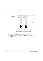
Page 56: ...st away from the processor unit a For CEX bus TB850 TB851 if cable TK850 is used see Figure 13 on page 58 and Figure 14 on page 59 If no units are used on the CEX bus no bus termination is required b...

Page 57: ...nal Battery Holder see Figure 33 on page 121 When the external SB821 battery unit is to be used install it according to the instructions in Installing the SB821 External Battery Unit on page 85 Note t...

Page 58: ...llation 58 3BSE 027 941 R301 Figure 13 TB850 Terminator for CEX bus male A TB850 male CEX bus termination unit is supplied with each package PM856K01 PM860K01 PM861K01 and PM864K01 of the PM8xx TP830...

Page 59: ...nfiguration 3BSE 027 941 R301 59 Figure 14 TB851 Terminator for CEX bus female F R Rx Tx RTS CI851 F R Rx Tx CI852 F R Tx1 Rx1 Tx2 Rx2 CI853 COM1 COM2 F R Rx Tx CI852 F R Tx1 Rx1 Tx2 Rx2 CI853 COM1 CO...

Page 60: ...Installing the PM8xx TP830 Processor Unit in Single Configuration Section 2 Installation 60 3BSE 027 941 R301 Figure 15 SA SB Connectors for Supervision Signals...

Page 61: ...se T TX max 100 m 110 yd The STP is suitable only in non industrial office environments Only use STP in a protected environment to connect to Commercial Off The Shelf COTS Ethernet components HUBS Tra...

Page 62: ...is used for serial protocols such as Modbus Siemens 3964R COMLI or custom design Table 8 TP830 COM3 Connections RJ45 connector Pin Designation Direction Description 1 RTS Out Request To Send 2 DTR Out...

Page 63: ...Control Builder to this port when connecting directly to the controller or when not required without the need use the remote tool connection via the Control Network Table 9 TP830 COM4 Connections RJ4...

Page 64: ...est away from the processor units or if no units are mounted directly to the CEX bus on the processor unit The CEX bus extension cable must be connected to both CPUs whether or not there are any other...

Page 65: ...e 17 7 The CPUs are supplied with internal back up batteries When the batteries are to be used place them in the Internal Battery Holder Figure 33 on page 121 When the external SB821 battery units are...

Page 66: ...dundant Configuration Section2 66 3BSE 027 941 R301 Communication Ports Same as for single configuration see Table 7 on page 61 Table 8 on page 62 and Table 9 on page 63 Figure 16 Connection of CPU re...

Page 67: ...and Installing the PM8xx TP830 Processor Unit in Single Configuration on page 56 2 Install a connector on the PROFIBUS DP cable Connect the cable screen to the ground terminal within the connector to...

Page 68: ...BUS DP must be connected with shielded twisted pair cables Table 10 CI851 PROFIBUS DP Connector PIN Designation Description 1 Shield Shield protective ground 2 Not Used 3 B line Receive Transmit Data...

Page 69: ...l on page 49 and Installing the PM8xx TP830 Processor Unit in Single Configuration on page 56 2 Install a connector on the FOUNDATION Fieldbus cable Connect the cable screen to the ground terminal wit...

Page 70: ...services and other fieldbus related items is available for FIELDBUS ONLINE via the Internet web site Powering Field Devices Field devices requiring power from the fieldbus need special power supplies...

Page 71: ...the connector to ground the screen via CI583 3 If cables longer than 15 m 16 4 yd are required then a short distance modem TC562 must be used In this case mount the modem onto a DIN rail in a suitable...

Page 72: ...n on page 56 2 Install a connector on the PROFIBUS DP V1 cable Connect the cable screen to the ground terminal within the connector to ground the screen via CI854 A connector with a switchable built i...

Page 73: ...st be connected with shielded twisted pair cables Table 13 CI854 PROFIBUS DP V1 Connector PIN Designation Description 1 Shield Shield protective ground 2 Not Used 3 RxD TxD P Receive Transmit Data P l...

Page 74: ...on the DIN rail see Mounting AC 800M Units onto DIN Rail on page 49 and Installing the PM8xx TP830 Processor Unit in Single Configuration on page 56 2 Connect the Ethernet twisted pair cable to the co...

Page 75: ...rail see Mounting AC 800M Units onto DIN Rail on page 49 and Installing the PM8xx TP830 Processor Unit in Single Configuration on page 56 2 Connect the S100 I O cable TK575 TK580 to the contact on the...

Page 76: ...isted pair is connected via the 10 Base T RJ45 connector located on TP853 For a description of the connector see Table 8 on page 62 Installing the CEX bus The CEX bus used for connection of communicat...

Page 77: ...en clusters to the fiber optical ModuleBus The fiber optical interface is intended for local distribution of I O clusters and for connection of engineered and standard drives Figure 17 on page 77 prov...

Page 78: ...115 V for 110 120 V AC b 230 V for 220 240 V AC default position on delivery 3 Connect the mains supply to the L ive and N eutral terminals 4 Connect the protective ground to the PE terminal 5 Connec...

Page 79: ...a A DIN rail end stop 1 b The terminal for the incoming protective ground 2 c The two terminals for the incoming Live and Neutral mains power 3 These terminals are equipped with built in jumpers which...

Page 80: ...ication if the power supply has been disconnected The fuse holders have built in red LEDs to indicate a ruptured defective fuse Figure 18 Installation of Mains Breaker Assembly MAINS To Power 1 2 3 4...

Page 81: ...following procedure to install the voting unit SS822 1 Mount the voting unit SS822 onto the DIN rail adjacent to the power supplies 2 Connect the voting unit to the selected SD821 822 823 power supply...

Page 82: ...an be supervised via the SS822 voting unit The supervision signals SA and SB from the SS822 are connected to the corresponding terminals of the CPU Figure 20 Redundant Power Supply Powering Redundant...

Page 83: ...dant power supplies powering AC 800M units Here the SA SB signals also indicate physical power supplies Figure 22 on page 84 shows one redundant power supply powering the AC 800M units and one for pow...

Page 84: ...F OK A B L SS822 F A B L L L L L L N L PE OK SD821 L L L L N L PE OK SD821 OK F OK A B L SS822 F A B L L L L L L N L PE OK SD821 L L L L N L PE OK SD821 SA SB L L Supervision signals to CPU unit via T...

Page 85: ...the batteries being connected in parallel it is necessary when using the external battery to remove the internal battery from the PM8xx in order to avoid reducing available memory back up time Install...

Page 86: ...ounted within cabinets Figure 23 on page 87 Wall Cabinet Single Power Supply Arrangement Figure 24 on page 88 Wall Cabinet Dual Power Supply Local Field Arrangement Figure 25 on page 89 Floor Mounted...

Page 87: ...llation Installation in Cabinets 3BSE 027 941 R301 87 Figure 23 Wall Cabinet Single Power Supply Arrangement 24 V Distribution Terminals SD821 Mains Breaker Unit Cable Duct Aluminum Profile Cable Expa...

Page 88: ...s Section 2 Installation 88 3BSE 027 941 R301 Figure 24 Wall Cabinet Dual Power Supply Local Field Arrangement Mains Breaker Unit SD821 24 V Distribution Units Units in Cabinet SD821 Field 24 V Distri...

Page 89: ...nstallation in Cabinets 3BSE 027 941 R301 89 Figure 25 Floor Mounted Cabinet Horizontal Unit Arrangement Voting Units SS822 Breakers Mains SD822 Redundant Power Supply Units Redundant Power Supply Uni...

Page 90: ...ontroller units there must be no obstruction within 50 mm 2 in above and 25 mm 1 in below the units as shown in Figure 26 on page 90 Note that the CPU and Communication Interfaces must be mounted on a...

Page 91: ...tion Control Software Documentation for available functionality The Control Builder Online Help facility provides detailed step by step information when creating an application for the AC 800M Control...

Page 92: ...igure 27 Example of AC 800M Controllers Connected to a Control Network I O AC 800M I O AC 800M STP AC 800M I O Switch Hub I O AC 800M I O AC 800M STP Switch I O AC 800M I O AC 800M STP Hub Within indu...

Page 93: ...for connection to the Control Network Both are RJ45 ports for Ethernet IEEE802 3 and connection is normally achieved using category 5 shielded twisted pair cable STP class 5 However as mentioned prev...

Page 94: ...ties are shown in Table 14 on page 94 For information on available serial protocols for the CI853 interface see COM3 above Table 14 Interfaces Available on the CEX bus Interface Number of Interfaces o...

Page 95: ...and Redundancy in the Control Builder M online help Remember that the Backup controller IP Addresses must be set in the primary Processor Unit This can only be done though the IPConfig tool There are...

Page 96: ...on on supported I O systems and units see Related Documentation on page 17 ModuleBus The ModuleBus in the AC 800M controller consists of one electrical and one optical unit Electrical ModuleBus see Fi...

Page 97: ...maximum 8 x 12 96 S800 I O units connected to an AC 800M Controller with single CPU configuration Figure 28 Electrical and Optical ModuleBus Configuration Maximum of 7 clusters groups Maximum of 12 x...

Page 98: ...s Each CPU is connected to one TB840 on each cluster see Figure 29 on page 98 Figure 29 Optical ModuleBus connection in redundant CPU configuration Maximum of 7 clusters groups Maximum of 12 x I O uni...

Page 99: ...site It is possible to connect the following I O systems to the PROFIBUS DP and PROFIBUS DP V1 S800 I O and or S800L I O via FCI refer to S800 I O documentation see Related Documentation on page 17 S...

Page 100: ...CI830 In single and redundant CPU configuration ABB Drives can be connected via PROFIBUS DP and CI830 See Figure 30 on page 101 Only Standard Drives can be connected to CI830 Fourteen 14 Standard Driv...

Page 101: ...CPU CI851 TB820 DI810 AI810 AO820 Max 12 units per cluster CI830 1 Segment of PROFIBUS DP Optical Optical DI810 AI810 AO820 PROFIBUS DP ABB Std Drive Branching Unit ABB Std Drive ABB Std Drive ABB Eng...

Page 102: ...ModuleBus the optical ModuleBus or the communication interfaces for PROFIBUS DP and PROFIBUS DP V1 Cabinet containing the AC 800M controller From this cabinet power may be required for Powering Units...

Page 103: ...s located in the cabinet The main configuration rule for this power supply is to retain the 24 V cables within the cabinet Powering Field Equipment outside the Cabinet This is intended for supplying p...

Page 104: ...ups then it is recommended to use separate power supplies for each field equipment group The use of fuses in the 24 V DC distribution system is not a fail safe measure If a short circuit occurs in one...

Page 105: ...24 V DC source This source is often common for many different types of plant equipment resulting in long power cables to the AC 800M Controller Furthermore heavy load changes can cause variations in c...

Page 106: ...Mains 24 V DC Distribution SD Voting Redundant Power Supplies Redundant Mains Power Supplies Terminals 24 V DC Distribution Terminals 24 V DC Distribution Terminals 82x Supply Power SD 82x SD 82x SD 8...

Page 107: ...SD Units Supply to Supply to 24 V DC Distribution 24 V DC Distribution Independent 82x SD Mains Mains Breaker Mains Breaker Supply to Units 24 V DC Distribution 24 V DC Distribution Independent Power...

Page 108: ...Powering from an External 24 V DC Source Section 3 Configuration 108 3BSE 027 941 R301...

Page 109: ...M8xx TP830 hardware units mounted on the AC 800M hardware platform constitute an AC 800M Controller LED Indicators Table 15 PM8xx LED Indicators Marking Color Function F ault Red Normal state OFF Re s...

Page 110: ...ware DUAL Yellow Lit when the CPU is running in redundant configuration and synchronized state 1 The software performs cyclic battery voltage level tests via a dedicated LED control input The battery...

Page 111: ...imary CPU in redundant configuration a switchover to the backup CPU will be initiated Table 17 PM8xx TP830 Connectors Marking Function L L SA SB External Power Supply Connection 24 V DC supply 0 V Red...

Page 112: ...unless marked Retain or Cold retain To initiate a warm restart disconnect the power supply for a few seconds Following a power failure the warm restart function will be automatically initiated on pow...

Page 113: ...ng the INIT push button less than 2 5 seconds 3 The system will be upgraded to synchronized CPU state once again Controller Reset The system stops The application program and variables are erased To i...

Page 114: ...in the Primary CPU Other HW error in the Primary CPU which causes CPU crash Severe communication errors on the Control network i e loss of both network ports in the Primary CPU Severe communication er...

Page 115: ...e Fault Finding Procedures on page 128 Table 18 AC 800M Controller Verification of Satisfactory System Operation LED Indicator Status AC 800M Controller Status PM8xx Processor Unit F ault Red LED must...

Page 116: ...ed LED must be OFF OK R un Green LED must be ON steady OK CI856 S100 I O Interface Unit F ault Red LED must be OFF OK R un Green LED must be ON steady OK C omm fail Red LED must be OFF OK CI857 INSUM...

Page 117: ...ng off the Primary CPU Check that the yellow DUAL LED subsequently lights up on both CPUs and that the PRIM LED lights up on the former Backup CPU now acting as Primary CPU For other units see Table 1...

Page 118: ...Verification of Redundant CPU Section 4 Operation 118 3BSE 027 941 R301...

Page 119: ...on page 21 Failure to do so could lead to personal injury or damage to equipment Table 20 Preventive Maintenance Frequency Schedule Frequency Equipment Procedure At regular user defined intervals Comp...

Page 120: ...Size AA IEC size R6 Lithium contents 0 3 g The battery must be exchanged whenever the PM8xx B attery LED flashes or is extinguished multiple or extended power cuts have occurred extended periods of sy...

Page 121: ...the PM8xx and remove the right hand cover 2 Identify and remove the internal battery 3 Insert a serviceable battery and check that battery polarity and orientation are correct 4 When power is re esta...

Page 122: ...5 Replace the PM8xx right hand cover and tighten the screw 6 Dispose of the run down Lithium battery in an approved manner Figure 34 Internal Battery Location here shown with PM860 F R P B INIT PM860...

Page 123: ...rity and orientation are correct Specifications for the external battery Type Low rate lithium battery 3 6 V 16 Ah Size ANSI Size D IEC R20 Lithium contents 5 6 g The battery must be exchanged wheneve...

Page 124: ...rnal battery 4 Read and comply with the Warning label text on the external battery 5 Carefully remove the battery 6 Insert a serviceable battery and check that battery polarity and orientation are cor...

Page 125: ...ction 5 Maintenance SB821 External Battery Unit 3BSE 027 941 R301 125 Figure 35 SB821 External Battery Unit Cover Removed SB821 3 6 V Lithium Battery Unit Note the warning text on the battery X1 B B S...

Page 126: ...in Redundant Configuration To exchange a halted processor unit 1 Disconnect the RCU Link Cable optical ModuleBus cable from the processor unit to be exchanged 2 Disconnect the Power Supply Socket from...

Page 127: ...the processor unit 3 Identify both the ModuleBus and CEX bus fuse holders to the right on the TP830 Baseplate Upper Fuse holder ModuleBus fuse 2AF Lower Fuse holder CEX bus fuse 3 15AF 4 Using a blade...

Page 128: ...r a unit failure on the CEX bus See Fault Finding Table 24 on page 130 Table 25 on page 131 Table 26 on page 134 Table 27 on page 135 and Table 30 on page 138 R un LED is OFF No application loaded on...

Page 129: ...nnected Connect the RCU Link Cable Different Control Software in the two CPUs Upgrade the CPUs with the same control software Table 23 Internal SB821 External Battery Fault Finding Fault Possible Caus...

Page 130: ...us have non illuminated LEDs Check the CEX bus fuse inside the PM8xx processor unit Initiate a reset signal INIT from the PM8xx processor unit Replace the CI851 unit F ault LED is ON Check all cables...

Page 131: ...d or configured Allow time for this to finalize If the condition persists and all units on the CEX bus have non illuminated LEDs Check the CEX bus fuse inside the PM8xx processor unit Initiate a reset...

Page 132: ...ttent Be incorrectly terminated Contain sections having reversed polarity due to incorrect connections Cause supply voltage drops due to damage or bad connections 3 The network power supply may be fau...

Page 133: ...unctions correctly A hand held fieldbus master unit should be used to make connections at different points in the network Locate the unserviceable section by reconnecting the sections one at a time In...

Page 134: ...ion interface cable is connected Check the hand shake signals The Tx Rx signals are flashing concurrently with transmission but the messages are not being received correctly by the connected device Ch...

Page 135: ...x processor unit Initiate a reset signal INIT from the PM8xx processor unit Replace the CI854 unit F ault LED is ON The CI854 board is in the process of being restarted or a fatal error occurred Allow...

Page 136: ...on the CEX bus is lit Check the CEX bus fuse inside the processor unit Initiate a reset signal INIT from the processor unit Replace the CI855 unit F ault LED is ON Check all cables and connectors for...

Page 137: ...unit is in the process of being configured Allow time for this to finalize If the condition persists and no other unit LED on the CEX bus is lit Check the CEX bus fuse inside the PM8xx processor unit...

Page 138: ...rom the processor unit Replace the CI857 unit F ault LED is ON Check all cables and connectors for damage and loose or poor connections Repair as necessary R un LED is flashing Check that the relevant...

Page 139: ...acility 12 x S800 I O units can be connected to the electrical ModuleBus Four on board communication ports CN1 CN2 Ethernet ports IEEE 802 3 10 Base T COM3 serial port RS232 C with modem support COM4...

Page 140: ...pical 300 mA max excl supply of ModuleBus and CEX bus see Appendix B Power Consumption Power Input Connector Four pin screw connector L L SA and SB Power Supply Requirements Inputs designated L and L...

Page 141: ...l and height vertically including lock mechanism Table 32 PM856 PM860 and TP830 Interfaces Technical data Item Value CN1 and CN2 Ethernet Communication Communication speed 10 Mbit s half duplex Signal...

Page 142: ...units Supply current Max 24 V 1 0 A short circuit proof fuse 2A fast Max 5 V 1 5 A short circuit proof Supply voltage variation 24 V follows the input power at L Optical ModuleBus I O capacity up to 7...

Page 143: ...ified in EMC Directive 89 336 EEC For more information regarding EMC and safety see Appendix D Directive Considerations LED Indicators See Table 15 on page 109 The figures given in Table 33 on page 14...

Page 144: ...n performance when executing an application program Using the same application program in PM856 and PM860 the difference in execution time can be expressed as Execution time in PM856 2 Execution time...

Page 145: ...battery back up facility 12 x S800 I O units can be connected to the electrical ModuleBus Four on board communication ports CN1 CN2 Ethernet ports IEEE 802 3 10 Base T COM3 serial port RS232 C with m...

Page 146: ...max excl supply of ModuleBus and CEX bus see Appendix B Power Consumption Power Input Connector Four pin screw connector L L SA and SB Power Supply Requirements Inputs designated L and L 24 V nominal...

Page 147: ...ack up on page 193 Weight 1200 g 2 6 lb package PM861K01 2800 g 6 1 lb package PM861K02 Dimensions W 119 x H 186 x D 135 mm 4 7 x 7 3 x 5 3 in Width is measured along the DIN rail depth from the wall...

Page 148: ...egarding electrical safety see Appendix D Directive Considerations LED Indicators See Table 15 on page 109 Performance Data The PM861 processor unit in single configuration has the same performance da...

Page 149: ...battery back up facility 12 x S800 I O units can be connected to the electrical ModuleBus Four on board communication ports CN1 CN2 Ethernet ports IEEE 802 3 10 Base T COM3 serial port RS232 C with m...

Page 150: ...mA max excl supply of ModuleBus and CEX bus see Appendix B Power Consumption Power Input Connector Four pin screw connector L L SA and SB Power Supply Requirements Inputs designated L and L 24 V nomin...

Page 151: ...ack up on page 193 Weight 1200 g 2 6 lb package PM864K01 2800 g 6 1 lb package PM864K02 Dimensions W 119 x H 186 x D 135 mm 4 7 x 7 3 x 5 3 in Width is measured along the DIN rail depth from the wall...

Page 152: ...mance Data The PM864 processor unit in single configuration has performance data which theoretically peaks at twice the performance compared to the PM860 The useful sustained performance improvement i...

Page 153: ...nit base prevents mounting of incompatible components Description The CI851 TP851 is used for connecting to remote I O Via an external gateway on PROFIBUS DP field instruments on PROFIBUS DP can be co...

Page 154: ...1 R301 Functional Block Diagram Figure 36 Block Diagram CI851 Bus interface Communication unit AnyBus M PROFIBUS DP 5 V 24 V Communication Extension Unit Communication Extension Baseplate Communicatio...

Page 155: ...controller Reset Rx Tx Yellow Transmission to or from the unit RTS Yellow Request to transmit from the unit Table 40 CI851 PROFIBUS DP Interface Specifications Item Value Type DP Master Class I Protoc...

Page 156: ...941 R301 Capacity Max 32 loads Protection Rating IP20 according to EN60529 IEC 529 Weight 700 g 1 5 lb package CI851K01 with CI851 and TP851 Dimensions W 59 x H 185 x D 127 5 mm W 2 9 x H 7 3 x D 5 0...

Page 157: ...FOUNDATION Fieldbus H1 FF H1 to the AC 800M The FF H1 has a communication speed of 31 25 kbit s and is intended for remote connection of field instruments The CI852 is connected to the bus via a trans...

Page 158: ...R301 Functional Block Diagram Figure 37 Block Diagram CI852 Bus interface Communication unit with FOUNDATION 5 V 24 V Communication Extension Unit Communication Extension Baseplate Communication line...

Page 159: ...een Operating Controlled by the Control Software Cleared by the Hardware during controller Reset Rx Tx Yellow Transmission to or from the unit Table 42 CI852 Foundation Fieldbus Interface Specificatio...

Page 160: ...Current consumption from CEX bus 24 V 140 mA typical 200 mA max Power dissipation 3 4W typical Protection Rating IP20 according to EN60529 IEC 529 Weight 700 g 1 5 lb package CI852K01 with CI852 and T...

Page 161: ...red Modem support Simple DIN rail mounting Transmission speed selectable between 75 baud and 115200 baud Ready made Software options for several protocols Pre set two letter Alpha code locking device...

Page 162: ...Block Diagram Figure 38 Block Diagram CI853 DC DC Bus interface Microprocessor with FPROM SRAM 5V 24 V Communication Extension Unit Communication Extension Base plate Communication lines Communication...

Page 163: ...eared by the Hardware during Reset of the controller Tx1 Yellow Lit if transmission to the COM1 port Rx1 Yellow Lit if receiving from the COM1 port Tx2 Yellow Lit if transmission from the COM2 port Rx...

Page 164: ...nning normally Green Exceptional fault Red Four traffic indictors Rx and Tx controlled by traffic pace Flashing yellow Connector Two RJ45 connectors on TP853 Current consumption from CEX bus 24 V DC 1...

Page 165: ...is used for connecting to remote I O Via an external gateway on PROFIBUS DP field instruments on PROFIBUS DP can be connected to AC 800M The TP854 Baseplate has two female DB9 connectors for connectin...

Page 166: ...ional Block Diagram Figure 39 Block Diagram CI854 CEX Bus Interface 5 V 3 3 V 24 V Communication Communication Extension Bus DC DC Converter CPU Kernel and Memory PROFIBUS Master ASIC Line Redundancy...

Page 167: ...Yellow Receive Data on Line A For each telegram received the LED flashes approximately 150ms RxB Yellow Receive Data on Line B For each telegram received the LED flashes approximately 150ms Table 46 C...

Page 168: ...om CEX bus 24 V DC 190 mA typical max 240 mA Power dissipation 4 6W typical Capacity Max 32 loads Protection Rating IP20 according to EN60529 IEC 529 Weight 700 g 1 5 lb package CI854K01 with CI854 an...

Page 169: ...3 can be used to connect an AC 800M to single or redundant MB 300 Networks This allows DataSet communication and transmission of time between AC 400 Master and AC 800M The TP853 Baseplate has two RJ45...

Page 170: ...eset R un Green Operating Controlled by the Control Software Cleared by the Hardware during controller Reset Tx1 Yellow flashing A yellow LED indicating transmission from the communication unit COM1 p...

Page 171: ...1 Functional Block Diagram Figure 40 Block Diagram CI855 Bus Interface 68360 QUICC Communication Processor Glue for Ethernet DC DC Converter 5V 5V Communication Extension Module Communication Extensio...

Page 172: ...uplex Status indicators Run normally green FAIL exceptionally red the four traffic indicators RX TX1 RX TX 2 COLL1 and COLL2 are yellow flashing controlled by the traffic pace Connector 2 RJ45 Current...

Page 173: ...n I O type and number of I O points Pre set two letter Alpha code locking device installed in unit base prevents mounting of incompatible components Description The CI856 TP856 connects S100 I O to AC...

Page 174: ...signation Color Function F ault Red Unit error detected Controlled by CI856 Software Set by the Hardware during controller Reset Cleared by the CI856 Software after successful startup R un Green Opera...

Page 175: ...Diagram Figure 41 Block Diagram CI856 CEX bus interface S100 I O bus interface 5 V 24 V Communication Extension Unit Communication Extension Baseplate S100 communication cable Communication Extension...

Page 176: ...ceptionally red the indicator TO are yellow flashing at S100 I O access time outs Connector 36 pin centerline miniature ribbon connector female Current consumption from CEX bus 24 V DC 120 mA typical...

Page 177: ...controller to INSUM through TCP IP over Ethernet and an INSUM TCP IP Gateway that has a LON interface communicating with the underlying INSUM system The TP853 Baseplate has two RJ45 Ethernet connector...

Page 178: ...ntrol Software Set and cleared by the Hardware during controller Reset R un Green Operating Controlled by the Control Software Cleared by the Hardware during controller Reset Tx1 Yellow flashing A yel...

Page 179: ...l Block Diagram Figure 42 Block Diagram CI857 Bus Interface 68360 QUICC Communication Processor Glue for Ethernet DC DC Converter 5V 5V Communication Extension Module Communication Extension Bus Commu...

Page 180: ...cators Running normally Green Exceptional fault Red Two traffic indictors Tx1 Rx1 controlled by traffic pace Flashing yellow Connector 2 RJ45 only COM1 is used Current consumption from CEX bus 24 V DC...

Page 181: ...3 24 Volts DC regulated 10A SD822 24 Volts DC regulated 5A SD821 24 Volts DC regulated 2 5A Accepted for SELV and PELV applications Safety Classification The Power Supply Units PSU are designed to mee...

Page 182: ...Appendix A Hardware Units 182 3BSE 027 941 R301 Figure 43 SD821 Connections for 2 5A Power Supply L L L L N L 103 mm 4 1 in 97 mm 3 8 in PE OK SD821 110 mm 4 3 in 230 Mains Voltage Selection Switch 1...

Page 183: ...Types SD821 SD822 and SD823 3BSE 027 941 R301 183 Figure 44 SD822 Connections for 5A Power Supply 44 mm L L L L N L 65 mm 2 6 in PE OK SD822 230 Mains Voltage Selection Switch 115 230 110 mm 4 3 in 10...

Page 184: ...cations as well as load sharing functions The three PSUs were designed as switch mode power converters converting AC mains supply voltage to a regulated 24V DC output Rated output capacity SD823 24 Vo...

Page 185: ...in the PSU circuit provides a soft start feature Consequently the controlled power on of a PSU will not trip fuses or ground fault circuit breakers In addition the normal disturbances that occur withi...

Page 186: ...meet the requirements of electrical safety publications for connection to the Phase Neutral terminals of the primary main network TN network 1 one fuse Recommended primary external fuse Micro Circuit...

Page 187: ...5 W Mains input voltage nominal 115 230 V AC 115 230 V AC 115 230 V AC Mains voltage variation allowed 85 110 85 110 85 110 Mains input voltage max a c 45 65 Hz 138 275 V AC 138 275 V AC 138 275 V AC...

Page 188: ...nting Dimensions Parameter SD821 Converter SD822 Converter SD823 Converter Dimensions Width HxD 125 x 110 mm 4 9 x 4 3 50 mm 2 0 in 65 mm 2 6 in 120 mm 4 7 in Mounting spacing W mm 10 mm 0 4 in 15 mm...

Page 189: ...e SS822 Voting Unit separates the redundant PSUs supervises the voltage supplied and generates supervision signals to be connected to the computer system Green LEDs mounted on the SS822 front panel pr...

Page 190: ...ax 120V and max 0 5A Contact rating d c Max 28V and max 1A min 1mA recommended min 5mA Table 57 SS822 Technical Data and Mounting Dimensions Parameter SS822 Rated output current A 20A Rated output vol...

Page 191: ...he manufacturer s documentation Westermo Using a modem allows distances between pieces of equipment to be as much as 18000m and depending on the distance can provide a data transmission speed of up to...

Page 192: ...hielded cable in an office environment A shielded cable is often given a higher capacitance and will therefore provide a higher data transmission speed Technical Data Table 58 TC562 Technical Data Typ...

Page 193: ...ail mounted and provided with a separate connecting cable TK821V020 2m 2 2yd in length 7HFKQLFDO DWD Table 60 SB821 External battery data Item Value Battery Type Low rate lithium 3 6V 16Ah Size ANSI s...

Page 194: ...01 DIN Rail TS 35 7 5 The figure below shows the profile and dimensions in mm in of the DIN rail TS 35 7 5 Normal supplied length is 2m 6 6ft to standard DIN 46 277 EN 50 022 Figure 49 DIN rail TS 35...

Page 195: ...e Units Miscellaneous Equipment 3BSE 027 941 R301 195 Miscellaneous Equipment TB850 Terminator for CEX bus Male Figure 50 TB850 Terminator for CEX male F R Rx Tx RTS CI851 F R Rx Tx RTS CI851 Terminat...

Page 196: ...B851 female Terminator for CEX bus is required when a TK850 extension cable is used Figure 51 TB851 Terminator for CEX female F R Rx Tx RTS CI851 F R Rx Tx CI852 F R Tx1 Rx1 Tx2 Rx2 CI853 COM1 COM2 F...

Page 197: ...X bus Extension Cable A 0 7m 2 3ft extension cable complete with connector type DB25P metal housing provides connectivity to Communication Interface units between adjacent DIN rails It is always used...

Page 198: ...ue Connectors One 9 pole male D sub DE9P One 8 pole RJ45 plug Weight 100 g 0 2 lb TK853V02 Length 2 0 m 6 56 TK853V02 Figure 52 TK853 Cable Characteristics 7 RTS 4 DTR 3 TD 5 0 V 2 RD 1 DCD 8 CTS Shie...

Page 199: ...ble Technical Data Item Value Connectors One 9 pole female D type One 8 pole RJ45 plug Weight 125 g 0 3 lb Length 3 0 m 9 84 Figure 53 TK212 Cable Characteristics 8 CTS 6 DSR 2 RD 1 DCD 5 0 V 3 TD 4 D...

Page 200: ...an A1 profile specifically designed for supporting DIN rails see Figure 54 on page 200 Refer to price list for additional information Key features of the Al profile are Simple mounting No drilling re...

Page 201: ...mains supply is Should the configuration be other than that stated detailed instructions for calculating current consumptions can be found in the following text The following tables present current c...

Page 202: ...age 203 The CPU supplies current via TP830 to units on the CEX bus and ModuleBus see Table 65 on page 203 Table 64 Current Consumption and Power Dissipation Data for AC 800M Units Unit Current at 24 V...

Page 203: ...the CPU power dissipation increases by 5W in addition to the values given in Table 64 on page 202 Table 65 CPU Current Supply to CEX bus and ModuleBus Bus 5 V 24 V ModuleBus max 1 5 A 1 1 Corresponds...

Page 204: ...0 TB840 and CI830 is accessible from the S800 I O documentation See Related Documentation on page 17 2 Calculate the current consumption at 24V for each electrical ModuleBus by adding Im I 24 V I 5 V...

Page 205: ...unching the AC 800M Controller Table 67 Recommended Components PROFIBUS DP Component Description PROFIBUS DP Due to the large selection of commercially available equipment manufactured to PROFIBUS DP...

Page 206: ...ufactured to FOUNDATION Fieldbus Standard IEC 1158 2 there is no recommendation for specific FOUNDATION Fieldbus components This statement covers all FOUNDATION Fieldbus equipment including FOUNDATION...

Page 207: ...sion required No configuration required Plug and play capability BayStack 350 24 24 port Star topology RJ45 Suitable for larger systems Supervision required Fiber optic capabilities No plug and play c...

Page 208: ...r topology RJ45 Suitable for larger systems Supervision required Fiber optic capabilities High Mean Time Between Failures MTBF Rugged Design for high temp use No plug and play capability CABLES Electr...

Page 209: ...0 022 DIN rail Accessories DIN rail end support device Phoenix UK 4 TG ST BE Standard commercially available components Cabinets ABB Automation Technology Products LV systems Wall cabinet RE820 for 3...

Page 210: ...ndard RKFK 3x1 5 mm2 RS232 C Unitronic CY 3 x 0 25 mm2 CY 7x 0 25 mm2 Belden Belden 8723 2 pair 0 34 mm2 Belden 9729 2 pair 0 22 mm2 Belden 9730 3 pair 0 34 mm2 FOUNDATION Fieldbus Unitronic Suitable...

Page 211: ...00 6 2 EMC Generic Immunity Standard Part 2 Industrial Environment Low Voltage Directive LVD Modules mentioned in this manual for which product or packing is CE marked comply with the LVD where applic...

Page 212: ...Low Voltage Directive LVD Appendix D Directive Considerations 212 3BSE 027 941 R301...

Page 213: ...locations is suitable for use in Class I Division 2 Groups A B C D or non hazardous locations only The products having the appropriate CSA and or UL markings that is Class I Division 2 Groups A B C D...

Page 214: ...Hazardous Location Approval Appendix E Standards 214 3BSE 027 941 R301...

Page 215: ...switched inductive or capacitive loads characterize an Industrial environment The associated magnetic fields are high Control products incl I O systems are normally intended for Industrial environmen...

Page 216: ...erative Range Climatic Conditions Temperature 25 to 70 C 25 to 60 C 3 Cabinets 1 5 to 40 C Units 2 5 to 55 C 10 to 40 C 3 EN 61131 2 Temp change Min 3 min within temp range 3 C min EN 61131 2 Humidity...

Page 217: ...Shock no package 150 m s2 11 ms 20 g 3 ms 3 DAT drives 5 g 3 ms 150 m s2 11 ms 20 g 3 ms 3 DAT drives 5 g 3 ms EN 61131 2 Fall in package 10 kg 1 m 10 40 kg 0 5 m 40 kg 0 25 m 100 kg 0 025 m EN 61131...

Page 218: ...ides to meet the EMC Directives Compliance is verified through conformity with the following minimum standards EMC Directive 89 336 EEC EN 61131 2 Product standard Programmable controllers EN 50081 2...

Page 219: ...tic Compatibility Conditions Emission Radiated Conducted Class A EN 55011 Immunity Radiated RF field 10V m EN 61000 4 3 ENV 50 204 Immunity Conducted RF field 10V EN 61000 4 3 Immunity ESD Electrical...

Page 220: ...rated value Main frequency a c 47 63 Hz 5 IEC 60255 6 Main voltage interruption a c Max 10 ms EN 61000 4 11 Overvoltage Category Permanently connected equipment Class III Overvoltage Category Non perm...

Page 221: ...cables All product connected cables should be routed at a distance of 30cm 12in from non product power cables heavy current cables and 10cm 4in from class 4 cables of relevant international immunity s...

Page 222: ...ons do not require additional lightning protection Additional lightning protection is always necessary when Cables extend beyond the area covered by the ground line network Cables are located above gr...

Page 223: ...dicators 159 Installation 69 Technical Data 159 CI853 Communication Interface 27 Fault Finding 134 Indicators 163 Installation 71 Technical Data 163 CI854 Communication Interface 27 Fault Finding 135...

Page 224: ...Ethernet Address 38 EUROPEAN UNION DIRECTIVE COMPLIANCE 16 External Battery How to Change 124 External Battery Module SB821 Installation 85 F Fault Finding External Battery 129 FOUNDATION Fieldbus CI...

Page 225: ...I O CI856 75 Voting Unit SS822 81 INSUM 15 Connection To 76 Installation 76 Internal Battery How to Change 120 L LED Indicators 109 Locking Device 50 Low Voltage Directive 211 M Mains Breaker Unit Ins...

Page 226: ...igurations 102 Powering Field Equipment 102 From External Source 105 Modules 102 Precautions 25 Processor Module PM8xx TP830 30 Product overview 27 PROFIBUS DP 15 27 99 Connection To 67 Installation 6...

Page 227: ...CI855 172 CI856 176 CI857 180 DIN rail 194 PM856 860 140 PM861 146 PM864 150 SB821 193 SD821 187 SD822 187 SD823 187 SS822 190 TC562 192 TK212 199 TK212 Technical Data 199 Tool Cable 65 TK850 CEX bus...

Page 228: ...QGH 228 3BSE 027 941 R301...

Page 229: ......

Page 230: ...ogy Products Mannheim Germany www abb de processautomation email marketing control prodcts de abb com Automation Technology Products V ster s Sweden www abb com processautomation email processautomati...

Reviews: