Section 2 Installation
Installing the ModuleBus
3BSE 027 941 R301
77
Installing the ModuleBus
The ModuleBus has an electrical and a fiber optical interface that are logically the
same buses. A maximum of 12 I/O units can be connected to the Electrical
ModuleBus and up to seven clusters to the fiber optical ModuleBus. The fiber
optical interface is intended for local distribution of I/O clusters and for connection
of engineered and standard drives.
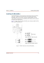
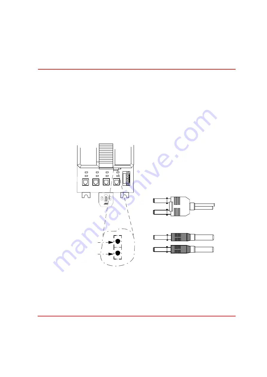
on page 77 provides details of the fiber optic connectors, together with the
PM8xx optical ModuleBus ports.
Figure 17. PM8xx Connectors for Optical ModuleBus
PM860
CN1
CN2
COM3
COM4
Tx
Rx
Tx
Rx
Tx
Rx
Tx
Rx
L+
L–
SA
SB
Rx
Tx
Duplex Fiber Optic Cable Connector
Simplex Fiber Optic Cable Connector
Summary of Contents for AC 800M
Page 1: ...ControlIT AC 800M Version 2 1 Controller Hardware Hardware and Operation...
Page 2: ......
Page 3: ...Controller Hardware Hardware and Operation ControlIT AC 800M Version 2 1...
Page 10: ...7DEOH RI RQWHQWV 10 3BSE 027 941 R301...
Page 20: ...Related Documentation About This Book 20 3BSE 027 941 R301...
Page 26: ...Operating Environment Safety Summary 26 3BSE 027 941 R301...
Page 42: ...Product Release History Section 1 Introduction 42 3BSE 027 941 R301...
Page 108: ...Powering from an External 24 V DC Source Section 3 Configuration 108 3BSE 027 941 R301...
Page 118: ...Verification of Redundant CPU Section 4 Operation 118 3BSE 027 941 R301...
Page 212: ...Low Voltage Directive LVD Appendix D Directive Considerations 212 3BSE 027 941 R301...
Page 214: ...Hazardous Location Approval Appendix E Standards 214 3BSE 027 941 R301...
Page 228: ...QGH 228 3BSE 027 941 R301...
Page 229: ......


