background image

________________________________________________________________________________________________________ 

AC500-eCo

                                                                - 8 -                                     


Hardware Introduction


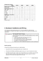
2. AC500-eCo Hardware Descriptions 


2.1 CPU Overview 

The CPU PM554 and PM564 is the central unit of the AC500 system with the onboard 
digital/analog inputs and outputs. The CPUs can be powered by 24V DC or 100-240V AC 
depending on different variant. 
The different between two CPU types is the onboard I/O type. 
 
Each AC500 CPU PM554 and PM564 can be used as 

  Bus Master within the control System AC500 together with CS31 or/and Modbus; 

  Stand-alone CPU. 


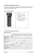
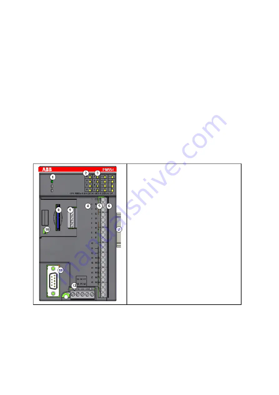
2.1.1 CPU components 

 
Take CPU PM554 as the example: 


1.

 3 LEDs to display the CPU statuses 

2.

 Allocation of signal name (with 4 and 5 

correspondences) 

3.

 yellow LEDs to display the inputs and the output 

(8 IN and 6 OUT) 

4.

 Allocation of terminal number 

5.

 Allocation of signal name 

6.

 9 and 11 poles I/O terminal block( fixed 

screw-type terminals) 

7.

 DIN rail 

8.

 SD Card (Option) 

9.

 COM2 + RTC (Option) 

10.

 RUN/STOP switch 

11.

 COM1 RS485 

12.

 Power supply terminal


Summary of Contents for AC500-eCo Series

Page 1: ...________________________________________________________________________________________________________ AC500 eCo 1 Hardware Introduction Hardware Introduction to AC500 eCo...

Page 2: ...please refer to the AC500 system manual Chapter 1 Introduction gives a brief overview of the AC500 System and describes the system structures Chapter 2 AC500 eCo Hardware Descriptions describes the te...

Page 3: ...OP 11 2 1 7 Status Display on the AC500 CPU 11 2 2 S500 eCo I O Modules Overview 12 2 2 1 I O Unit components 12 2 2 2 S500 eCo I O Modules Assortments 12 3 Hardware Installation and Wiring 13 3 1 Har...

Page 4: ...he system structures 1 1 AC500 System Overview Figure 1 AC500 PLC Overview This Figure shows the ABB AC500 PLC family different CPU Type with different performance and memory The principle AC500 PLC s...

Page 5: ...3 0 3 0 15 0 15 0 01 0 01 Floating point 6 6 6 3 3 0 02 0 02 Number of centralized inputs outputs max binary inputs 232 232 320 320 320 320 320 binary outputs 174 174 240 240 240 240 240 analog input...

Page 6: ...AI523 AX521 AX522 AO523 AI561 AO561 AX561 AI562 AI563 Number of Channels per Module analoge Inputs 16x 4x 8x 4x 4x analoge Outputs 4x 8x 16x 2x 2x Inputs single configurable 2 5V 2 5V x x 5V 5V x x 0...

Page 7: ...s The S500 I O modules 14 new S500 eCo modules are in small housing half of previous S500 I O module with different versions and new features The new CPUs PM554 PM564 and the S500 eCo I O modules need...

Page 8: ...CPU types is the onboard I O type Each AC500 CPU PM554 and PM564 can be used as Bus Master within the control System AC500 together with CS31 or and Modbus Stand alone CPU 2 1 1 CPU components Take C...

Page 9: ...pped with a filter function to prevent incorrect operation caused by chatter or noise in the input signal The user can select an input time constant of 0 1ms 1ms 8 ms or 32 ms it s have two configurab...

Page 10: ...ystem bus I O Bus The I O Bus is I O data bus for the S500 Input Output expansion modules Through this bus I O and diagnosis data are transferred between the AC500 CPU and the S500 I O expansion modul...

Page 11: ...pper left side indicate the module operation status and 16 LEDs indicate the status of Input Output signals LED Status Color LED ON LED OFF PWR 24 V DC or 100 240V AC power supply is provided Red volt...

Page 12: ...LEDs to display the signal statuses 4 Allocation of terminal number 5 Allocation of signal name 6 9 and 11 poles I O terminal block screw type terminals 2 2 2 S500 eCo I O Modules Assortments Digital...

Page 13: ...ischarge This equipment is sensitive to electrostatic discharge which can cause internal damage and affect normal operation Follow these guidelines when you handle this equipment Touch a grounded obje...

Page 14: ...the controller is energized 3 1 1 DIN Rail Mounting re Mounting Mounting on DIN rail Step 1 Install the 7 5 mm or 15 mm DIN Rail Step 2 Snap the AC500 CPU on the DIN Rail The AC500 CPU will be placed...

Page 15: ...6DI DO T DO571 8DO R o connect a 100 240 VAC sensor or actuator to the CPU DI571 8DI DO572 8DO Triac DO571 8DO R to connect an analog 24 VDC sensor or actuator to the CPU AI561 4AI AO561 2AO AX561 4AI...

Page 16: ...screws Wall Mounting Accessories TA566 must be inserted at the rear side first 1 The Wall Mounting Accessories TA566 is snapped on the rear side of the CPU or the I O modules Figure 8 Wall mounting o...

Page 17: ...3 2 1 Power Supply Wiring AC500 CPUs PM554 and PM564 use two kinds of power supply voltage 1 24VDC 2 100 240VAC IMPORTENT For 24V DC variant exceeding the maximum power supply voltage 30V DC for proce...

Page 18: ...epending on how many poles on the terminal block there were three kinds 5 poles for the power supply 9 poles for the inputs of the S500 modules 11 poles for the outputs of the S500 modules Depending o...

Page 19: ...6 max analog inputs outputs 2 1 Max number of centralized inputs outputs Digital inputs 224 8 224 8 224 8 Digital outputs 168 6 168 6 168 6 Analog inputs 112 112 112 2 Analog outputs 112 112 112 1 Max...

Page 20: ...Kan le zus tzlich konfigurierbar als Schneller Z hler Puls Weiten Modulbeiod er Drehzahl Zeit und Frequenzmesser Interrupt Eingang Interrupt response time Belegt max 1 DO bzw DC bei Nutzung als Z hler...

Page 21: ...C oder 250 V AC 19 2 V DC bei maximum Strom Ausgangsverz gerung aus ein 50 s 0 2ms AC cycle 50 s 50 s ein aus 200 s 0 2ms AC cycle 200 s 200 s Umschalten 10 ms bei nodermaler Spannung 10 ms bei noderm...

Page 22: ...ensdauer Schaltspiele mechanisch 100 000 00 0 100 000 00 0 unter Last 100 100 Funkenl schung bei induktiver AC Last Externe Ma nahme entspreche nd der geschaltete n Last Entmagnetisierung bei induktiv...

Page 23: ...hlung Die nar rliche Konvektionsk hlung darf nicht durch Kabelkan le oder andere Schaltschrankeinbauten behindert werden AIO E A Module analog Tabelle 2 analoge E A AI561 AO561 AX561 AI562 AI563 anal...

Page 24: ...angsfilters Spannung 100 s Strom 100 s Spannung 100 100 s Strom 100 s Wandlungszyklus 2 ms ber 8 AI 8 AO bei Pt Ni 1 s berspannungsschutz Up to 30VDC Up to 30VDC Konfigurationsm glichkeit pro AO Pro M...

Page 25: ...61 8 24 V DC 1TNE968902R2101 DI562 16 24 V DC 1TNE968902R2102 DI571 8 100 240 V AC 1TNE968902R2103 DO561 8 24 V DC Transistor 24 V DC 0 5 A 1TNE968902R2201 DO571 8 Relay 24 V DC 120 240 V AC 2A 1TNE96...

Page 26: ...R3107 TA567 Option cover for AC500 CPU module 1TNE968901R3202 TA568 5 poles terminal block for AC500 CPU power supply Cable Front Screw Side 1TNE968901R3108 4 3 Guidelines of Safety Important user inf...

Page 27: ...equipment is supplied as open type equipment It must be mounted within an enclosure that is suitably designed for those specific environmental conditions that will be present and appropriately designe...

Page 28: ...roblem free functioning of the devices at their work location can be ensured by observing the following instructions Qualified personnel Both the control system AC500 and other components in the vicin...

Page 29: ...t basically be able to flow off to the earthing in this respect see also VBG 4 and the relevant VDE regulations In the description special attention must be paid to designs using electrical isolation...

Page 30: ...tteries Lithium batteries are primary cells and cannot be recharged Attempts to charge lithium batteries lead to overheating and possible explosions Dispose of lithium batteries environmentally consci...

Page 31: ...tomers are requested to provide the following Provide all required application documentation and information Provide access if required to the system being examined Assign key individuals to assist as...

Page 32: ...lease find detailed information in our seminar brochure You can order this brochure from the address given above or from every ABB STOTZ KONTAKT GmbH office or you can download it from our Internet we...

Page 33: ...ocols are supported as a standard feature as application layer Modbus TCP Topology Star or ring shaped using Ethernet hub or switch Data transmission Max 10 MB s with 10 Base T and max 100 MB s with F...

Page 34: ...proprietary master slave field bus It is characterized by simple handling easy configuration and inexpensive installation The COM1 interface of the AC500 can be configured as a CS31 field bus master C...

Reviews: