background image

____________________________________________________________________________________________________ 

Getting Started with AC500-eCo Starter-Kit

                                                                                  - 21 -   


3.2.4 Opening the function Block Diagram Editor and Program 

 
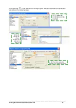
1.From the Resources we now want to switch to the Function Block Diagram editor: Click on 
the 

  tab and then double click on the entry PLC_PRG (PRG). The Function Block 

Diagram editor is opened. 
 
2. Following shows you how to created the program.   


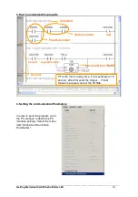
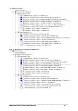
3.Position the mouse cursor into the insertion mark 

  of network “0001” and click the 

right mouse button, select “network (after)”, you can now program in second network . 

after click shows   


Then you have 0002 as the second network after the first network: 0001. 


Summary of Contents for AC500-eCo Starter-Kit

Page 1: ...____________________________________________________________________________________________________ Getting Started with AC500 eCo Starter Kit 1 Getting Started with AC500 eCo Starter Kit ...

Page 2: ...rmation of the hardware and how to mounting the Starter Kit After that when you want directly program you can start with the chapter 3 Chapter 2 AC500 Software Description gives general information about the PS501 Control Builder Chapter 3 Programming Example gives 2 little examples to describe how to create a program with the AC500 eCo Starter Kit The Appendix Chapter 4 gives the further informat...

Page 3: ...electric Motor Initiation Control and Rotation 11 3 2 Simple Example for Getting started 18 3 2 1 Creating a new Project 18 3 2 2 Saving the Project to the PC 19 3 2 3 Specifying the Hardware Configuration 20 3 2 4 Opening the function Block Diagram Editor and Program 21 3 2 5 Compiling the Project 22 3 2 6 Setting the Communication Parameters 23 3 2 7 Testing the Program without PLC Hardware conn...

Page 4: ...C500 brochure 8 Screw driver Short introduction about the CPU PM554 R Power Supply 100 240V AC Onboard I O 8 digital inputs 6 digital relay outputs Interrupt inputs 4 configurable I0 I3 Fast counter I0 as a configurable fast counter input Output Voltage 24V DC PWM 2 configurable PWM outputs LED displayed for the signal status Elements of the PM554 R 1 LED PWR is green CPU power on 2 LED RUN is gre...

Page 5: ... connected to a 5 pole removable terminal block At first you must insert the 5 pole terminal block to the CPU The 5 poles from left to right are L N FE L and M FE is for functional earth L and N are connected to AC power supply source L and M are for the voltage outputs 24V DC and 0V After wiring you will see the LED PWR turn to green that means Power ON like follow 2 Wiring the onboard I Os of th...

Page 6: ...th AC500 eCo Starter Kit 6 The following figure shows the electrical connection of the onboard digital relay outputs Figure 2 Wiring of the PM554 R onboard digital outputs source 3 Connect the PLC with your PC Figure 3 PLC connect the PC with programming cable 4 Install the drive of the USB cable TK503 Programming cable ...

Page 7: ...501 Figure 4 Installation Menu Clicking on Read me for installation to display the read me file containing additional information regarding the installation of the software Sequence of the installation The following installation menus are available 1 Step 1 Installation of the Control Builder software 2 Step 2 Installation the GSD and EDS files 3 Opt 1 Installation of the documentation If you requ...

Page 8: ...ironments of advanced programming languages Figure 5 Features of PS501 This software has following features Programming in conformity with IEC 61131 3 Five standardized programming languages Function Block Diagram FBD Instruction List IL Ladder Diagram LD Structured Text ST and Sequential Function Chart SFC free graphical function chart CFC Debugging functions for the program test Single step Sing...

Page 9: ...ange moving elements bitmaps text display allows input of set point values and display of process variables read from the PLC dynamic bar diagrams alarm and event management function keys and ActiveX elements Configurators of the communication interfaces Integrated configurator for Ethernet Modbus and CS31 Open interfaces DDE and OPC Programming Serial or via Ethernet networks Engineering interfac...

Page 10: ...erview A project is put into a file named after the project The first POU Program Organization Unit created in a new project will automatically be named PLC_PRG The process begins here and other POUs can be accessed from the same point programs function blocks and functions PS501 Control Builder provides extensive online help Use the Help button of the menu bar or press F1 to obtain the informatio...

Page 11: ...o the forward network 4 or reversing network 5 rotation control This program used LD Ladder Diagram as program language Following symbol table we use for all onboard I Os configuration Symbol name Comment in PLC configuration Meaning ObDI00 Motor START with SB1 Switch SB1 to start the Motor ObDI01 Triangle initialization START with SB2 Switch SB2 to start the Y Δ initialization ObDI02 Transistor O...

Page 12: ...0 eCo Starter Kit 12 1 Open a new project 2 Open the program Motor from the CD Click on the open folder button in the Tool bar or click file open and select the program Motor pro After that the program has been downloaded into your PC 1 Open the PS501 Control Builder software Start Program 3S Software CoDeSys V2 3 CoDeSys V2 3 ...

Page 13: ...e communication Parameters In order to send the program out of the PC we have to define the PC interface settings Select the menu item Online Communication Parameters Network Contact negated Contact Series contact Comment Coil Parallel contact Function Block TIMER PT is the turn on delay time in this example is 15 second After that enter the Output T36 Q means the output value of the TON36 ...

Page 14: ...e steps below Confirm your settings with OK 5 Compiling the project In order to build the project select the menu item Project Build If no errors were detected the message 0 errors 0 warnings is displayed in the message box 6 Downloading the program to the PLC Now we can download the program to the PLC Change the RUN STOP switch to the RUN mode First we have to load the program to the controller T...

Page 15: ...w all in PLC browser in Resources You can also find all commands of the PLC browser by click the button on the right side More detailed Error code information please check Appendix 4 3 8 Check the program with the PLC In PLC Configuration windows you can change the digital input status to check your program First you change the onboard digital inputs ObDI00 ObDI01 and ObDI02 status from 0 to 1 in ...

Page 16: ...____________________________________________________________________________________________________ Getting Started with AC500 eCo Starter Kit 16 After 15 seconds start the triangle initialization ...

Page 17: ...____________________________________________________________________________________________________ Getting Started with AC500 eCo Starter Kit 17 After that the motor can forward rotation Or reversing ...

Page 18: ...arter Kit 18 3 2 Simple Example for Getting started Now we will learn how to program with the PS501 Control Builder In this example we use the programming language FBD 3 2 1 Creating a new Project 1 Open the Software 2 Create the new project 1 Open the PS501 Control Builder software Start Program 3S Software CoDeSys V2 3 CoDeSys V2 3 ...

Page 19: ...his example only PLC_PRG is used we do not need to add more POUs moreover the FBD is used for programming in this POU Finally click the OK button The PLC_PRG is the main program Note All necessary libraries are loaded automatically You have finish to open a new project 3 2 2 Saving the Project to the PC Before designing we should save the project click the shortcut Save on the top of the window or...

Page 20: ...3 2 3 Specifying the Hardware Configuration In order to specifying the hardware configuration you must configuring the I O parameters and define the symbolic names for I Os Use the same procedure like above for the rest necessary inputs and outputs Choose the I05 for Input5 O00 and O01 for Output0 and Output1 Now you finish the AC500 basic set up ...

Page 21: ...itch to the Function Block Diagram editor Click on the tab and then double click on the entry PLC_PRG PRG The Function Block Diagram editor is opened 2 Following shows you how to created the program 3 Position the mouse cursor into the insertion mark of network 0001 and click the right mouse button select network after you can now program in second network after click shows Then you have 0002 as t...

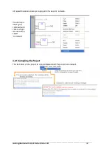
Page 22: ...______ Getting Started with AC500 eCo Starter Kit 22 4 Repeat the seconds steps to program the second network You can also insert your comment with click the right mouse button select Comment 3 2 5 Compiling the Project The definition of the project is now completed and the project can be built ...

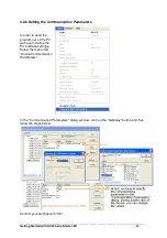
Page 23: ...Starter Kit 23 3 2 6 Setting the Communication Parameters In order to send the program out of the PC we have to define the PC interface settings Select the menu item Online Communication Parameters In the Communication Parameters dialog window click on the Gateway button and then follow the steps below Confirm your settings with OK ...

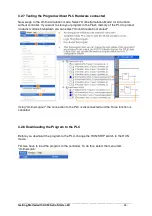
Page 24: ...on without controller If you want to store your program in the Flash memory of the PLC to protect it against voltage breakdown you can select Online Create boot project Using Online Logout the connection to the PLC is disconnected and the Force function is canceled 3 2 8 Downloading the Program to the PLC Before you download the program to the PLC change the RUN STOP switch to the RUN mode First w...

Page 25: ...appear select the menu item Online RUN Now your PC has been connected with the PLC 3 2 9 Program Visualization 1 A visualization object is a CoDeSys object which is managed in the Visualization register of the Object Organizer In order to create a visualization object in the Object Organizer you must select the register card for in the Object Organizer 2 Enter the visualization element ...

Page 26: ...tting Started with AC500 eCo Starter Kit 26 3 Double click on the elements for configuring this element Establishes its parameter according to the following steps Set the communication between this element and I04 To write the comments on the element When I04 change the status change this element s color ...

Page 27: ...teps it s different on the parameter setting In category Text enter digital output00 instead of digital input04 In category Variables enter O00 instead of I04 Use red as inside color and choose green as the alarm color Using the same procedure for OutputO01 Then we finish our program Red means Outputs are now 0 Other category we using default for this example After of all click OK to confirm the c...

Page 28: ...ting Started with AC500 eCo Starter Kit 28 5 Click Online Login and then Online Run to visualization our Program 3 2 10 Change the Inputs Status with the Simulator When you put the 6 switch of the simulator from STOP mode to RUN mode e g I05 from 0 to 1 you will also see the changes like the figure above ...

Page 29: ..._________________________________________________________________________ Getting Started with AC500 eCo Starter Kit 29 3 2 11 Exit the Software To exit the software select the menu item File Exit But before that you must logout ...

Page 30: ...erg SHL in n in gets shifted to the left by n bits BYTE WORD DWORD SHR Bitwise right shift of an operand erg SHR in n in gets shifted to the right by n bits BYTE WORD DWORD ROL Bitwise rotation of an operand to the left erg ROL in n in will be shifted one bit position to the left n times while the bit that is furthest to the left will be reinserted from the right BYTE WORD DWORD ROR Bitwise rotati...

Page 31: ... integral number type to another number type REAL_TO LREAL_TO conversions Converting from the variable type REAL or LREAL to a different type STRING BOOL REAL and LREAL TIME_TO TIME_OF_DAY Conversion Converting from the variable type TIME or TIME_OF_DAY to a different type DWORD For the STRING type variable the result is a time constant DATE_TO DT_T O Conversions Converting from the variable type ...

Page 32: ...ction of sine of a number IN can be BYTE WORD DWORD INT DINT REAL SINT USINT UINT UDINT OUT must be type REAL ACOS Returns the arc cosine inverse function of cosine of a number The value is calculated in arch minutes IN can be BYTE WORD DWORD INT DINT REAL SINT USINT UINT UDINT OUT must be type REAL ATAN Returns the arc tangent inverse function of tangent of a number IN can be BYTE WORD DWORD INT ...

Page 33: ...8 24 V DC 1TNE968902R2101 DI562 16 24 V DC 1TNE968902R2102 DI571 8 100 240 V AC 1TNE968902R2103 DO561 8 24 V DC Transistor 24 V DC 0 5 A 1TNE968902R2201 DO571 8 Relay 24 V DC 120 240 V AC 2A 1TNE968902R2202 DO572 8 Triac 100 240 V AC 0 3A 1TNE968902R2203 DX561 8 8 24 V DC Transistor 24 V DC 0 5 A 1TNE968902R2301 DX571 8 8 24 V DC Relay 24 V DC 120 240V AC 0 5 A 1TNE968902R2302 DC561 16 24 V DC Tra...

Page 34: ...Front Cable Front 1TNE968901R3105 TA565 11 11 poles terminal block for S500 I O modules Spring Front Cable Front 1TNE968901R3106 TA566 Wall Mounting Accessory for AC500 CPU and S500 I O modules 1TNE968901R3107 TA567 Option cover for AC500 CPU module 1TNE968901R3202 TA568 5 poles terminal block for AC500 CPU power supply Cable Front Screw Side 1TNE968901R3108 4 3 Detail Faulty Code Error class E1 t...

Page 35: ...protocols are supported as a standard feature as application layer Modbus TCP Topology Star or ring shaped using Ethernet hub or switch Data transmission Max 10 MB s with 10 Base T and max 100 MB s with Fast Ethernet Transmission media Twisted pair cables with RJ45 connector The maximum cable length is 100 m for 100 MB s Diagnostics Detailed diagnostic messages for rapid trouble shooting are shown...

Page 36: ...s a proprietary master slave field bus It is characterized by simple handling easy configuration and inexpensive installation The COM1 interface of the AC500 can be configured as a CS31 field bus master Communication Is handled using polling i e the master sends a request to the slave and then receives the response The CS31 operating mode of COM1 is set using the engineering tool Topology Multi po...

Page 37: ...the temperature is between 60 C and 120 C the user open the switch of the tank the water will flow into the user s part The following components are required for this example One CPU type PM554 One 100 240V AC power supply One S500 digital I O module DX561 One S500 analog input module AI561 One S500 analog RTD input module AI562 with Ni1000 50 C 150 C 2 wire A PC with the programming software PS50...

Page 38: ...AC500 Control Builder programming software click to create a new project Select the CPU type Select the program language Select the desired CPU in this example PM554 in the appearing window Then in the appearing window click OK Keep the settings PLC_PRG and Program for the name and the type for this new POU select ST for the language of the POU and confirm with OK The ST Editor is opened ...

Page 39: ...iguration Click on double click the object PLC Configuration If the AC500 compact folder in the PLC configuration tree is closed click on the symbol The I O devices connected directly to the I O bus of the CPU will be entered click on I O Bus FIX and press the right mouse button to add the expansion module in this example we choose DX561 AI561 and AI562 Save the project with menu item file save as...

Page 40: ...__________________________________ Getting Started with AC500 eCo Starter Kit 40 3 Symbolic comments for I Os Click once on digital output 0 for onboard I Os by Base parameters window enter waterLevel ALARM for the comment Complete your input by pressing the Enter key ...

Page 41: ...________________________________________________ Getting Started with AC500 eCo Starter Kit 41 Use the same procedure for other onboard outputs Click once on analog input 0 of AI561 by Base parameters window enter Fluid position gathering for the comment ...

Page 42: ...d of not used Complete your input by pressing the Enter key Use the same procedure to configure the analog input of AI562 Only use Temperature gathering for the comment and choose 2 wire NI1000 50 150deg for the value 5 Opening the ST Structured Text editor From the resources we now want to switch to the structured editor click on the tab and then double click on the entry PLC_PRG PRG The structur...

Page 43: ...t_Control To do this position the mouse cursor to the POUs Folder right click on the mouse and select Add object In the appearing window enter Fluid_Position_Control for the name of the first part of the program Use the same procedure for part 2 and part 3 Then we have the structure of the whole program 7 Programming Click once on tab in the right window you can enter the program for first part of...

Page 44: ...__________________________________________________________________________________________________ Getting Started with AC500 eCo Starter Kit 44 Use the same way to create the next 2 parts of this program ...

Page 45: ...have four programs but only the PLC_PRG PRG is the main program others are the user defined program These three programs will be called by the main program so we can put them into a folder To do this mouse right clicks on the Folder POUs and chooses New Folder Right mouse click on the New Folder and choose Rename Object Rename this Folder as Real_Control ...

Page 46: ...fined programs in the Real_Control folder Now we see a main program PLC_PRG and three user defined program under Real_Control folder In order to program the main program double click on the PLC_PRG PRG In the programming window mouse right click and choose Input assistant In the appearing window choose User defined Programs Fluid_Position_Control PRG and confirm with OK ...

Page 47: ...00 eCo Starter Kit 47 And choose the other program sequential After that we finish our main program The programming of the project is now completed 8 Compiling the project In order to build the project select the menu item Project Build If no errors were detected the message 0 errors 0 warnings is displayed in the message box ...

Page 48: ...nnect the AI561 Input with DX561 with power supply Connect the AI562 Input with AI561 with power supply Further wiring information of the CPU and the I O modules please refer to the system data of the AC500 PLC CAUTION Failure to heed precaution can result in injury to people or product to property 8 Downloading the program to the PLC After us wiring the hardware we can now download the program to...

Reviews: