background image

AC500-S

Usage of AC500 Digital Standard I/Os 

in Functional Safety Applications 

up to PL c (ISO 13849-1)

Application Note

Summary of Contents for AC500-S

Page 1: ...AC500 S Usage of AC500 Digital Standard I Os in Functional Safety Applications up to PL c ISO 13849 1 Application Note...

Page 2: ...5 Definitions expressions abbreviations 4 1 6 References Related documents 5 2 Usage of digital standard I Os in functional safety applications up to PL c _____6 2 1 Overview 6 2 2 Task 8 2 3 Solution...

Page 3: ...ys tem costs and reduce control cabinet dimensions in some customer applications We analyzed a possible usage of AC500 digital standard I Os to realize functional safety functions This application not...

Page 4: ...vings or for indirect or follow up damages or losses no matter of what kind 1 4 Important user information This documentation is intended for qualified personnel familiar with Functional Safety You mu...

Page 5: ...verage DPRAM Dual ported Random Access Memory IEC International Electro technical Commission Standard I O Input Output EMC Electromagnetic compatibility FB Function Block FSDT Functional Safety Design...

Page 6: ...in practice and results in very limited cost saving two output channels from two different standard output modules will be needed contact ABB technical support at www abb com PLC for more details As...

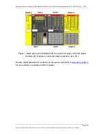
Page 7: ...eproduction use or disclosure to third parties without express authority is strictly forbidden 2015 ABB Ltd Figure 1 Basic setup with AC500 AC500 S modules for usage of AC500 digital standard I O modu...

Page 8: ...to PL c is needed to satisfy specific customer requirements e g limited space in the control cabinet to add additional digital safety I O mod ule cost saving etc Customer benefits from using spare AC...

Page 9: ...his document Reproduction use or disclosure to third parties without express authority is strictly forbidden 2015 ABB Ltd Figure 2 Relationship between Categories DCavg MTTFd of each channel and PL fr...

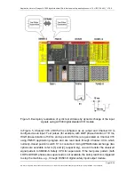
Page 10: ...the loss of the safety function between the checks The loss of safety function is detected by the check Category 2 architecture realization using AC500 AC500 S modules see Figure 1 is shown in Figure...

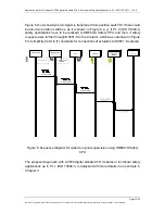
Page 11: ...realization of this measure in AC500 AC500 S setup is presented in Figure 5 and is based on some assumptions which are later described in Chapter 3 in details Generation of dynamic pulses is done e g...

Page 12: ...output and Channel C0 is configured as an input Test pulses for example with LOW phase duration of 10 ms HIGH phase duration of 50 ms and a period of 60 ms are generated on Channel C16 using PM573 ap...

Page 13: ...osition switches as it is shown in Figure 6 e g if PL d ISO 13849 1 safety applications have to be realized to SM560 S Safety CPU and then if safety request exists further through DX581 S to the actua...

Page 14: ...ide only a safety analysis with the supporting calculation for the Safety PLC part in the safety loop which means that values for sensor and actuator parts will be omitted for simplicity We aim to rea...

Page 15: ...hange of the input signal for fault detection is implemented for digital standard input channel on DC523 module as it is shown in Figure 5 This test signal is able to detect Stuck At 1 errors on the p...

Page 16: ...pulse generation task on standard CPU program will influence the generated test pulse pattern The supervision of the test pattern length of LOW and HIGH phases will be implemented on the Safety CPU T...

Page 17: ...e that proper Min Update Time setting is selected for SM560 S Safety CPU in Automation Builder 2 or 3 ms are recom mended for the proposed example NOTICE Make sure that proper cycle time value is used...

Page 18: ...as part of the safety application program becomes Dis crepancyTime T 400ms see Step 4 above These values shall be further used in SFRT and fault reaction time calculations NOTICE The test rate the tes...

Page 19: ...ady covered for AC500 S Safety PLC modules like SM560 S and DX581 S which are certified for up to PL e ISO 13849 1 and SIL CL 3 IEC 62061 safety applications The AC500 product requirements for the con...

Page 20: ...r 3 4 1 As for SFRT input part it means SFRT up to SM560 S Safety CPU only one shall add the fault error reaction time for DC523 path 400 ms in the given example refer to Chapter 3 4 1 to a LOW phase...

Page 21: ...significantly less than the MTBF The following MTTFd values were used in the calculation for AC500 standard modules all AC500 modules which are involved in the internal communication of dynamic test p...

Page 22: ...PFHavg value of 3 32E 7 1 h for the safety function actuation of the Off switch S1 which leads to SS1 Safe Stop 1 with a controlled stop of the motor within a maximum permissible time NOTICE The missi...

Page 23: ...tand ard I O modules in functional safety applications up to PL c ISO 13849 1 However the implementation verification and validation of the approach in practice according to ISO 13849 1 and or IEC 620...

Page 24: ...ith regard to purchase orders the agreed particulars shall prevail ABB AG does not accept any responsibility whatsoever for potential errors or possible lack of information in this document We reserve...

Reviews: