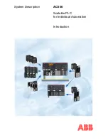
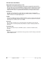
background image

System Description 

AC500 


Scalable PLC 
for Individual Automation 
 
 
Introduction 


Summary of Contents for AC500 Series

Page 1: ...System Description AC500 Scalable PLC for Individual Automation Introduction...

Page 2: ......

Page 3: ...ment of the Lithium battery 1 39 Insertion of the SD Memory Card 1 41 Mounting the system 1 42 AC500 system dimensions 1 48 Setting the FBP slave address 1 50 Status display and error indication on th...

Page 4: ...____________________________________________________________________________________________________________ G1 Introduction to AC500 1 2 AC500 Issued 07 2006...

Page 5: ...of the AC500 system CPUs of three different performance classes Couplers for various bus systems Fieldbus systems PROFIBUS DP CANopen DeviceNet Ethernet couplers Central expansion One CPU supports di...

Page 6: ...ssued 07 2006 AC500 system overview AC500 is a complex state of the art system providing extensive automation potential for your plant Figure AC500 system The following pages provide a summary of all...

Page 7: ...200 R0100 PM582 CPU memory 512 kB 24 V DC Memory Card Slot interfaces 2 x RS 232 485 programming Modbus CS31 1 x FBP Display PM582 ETH 1SAP 140 200 R0170 PM582 ETH CPU memory 512 kB 24 V DC Memory Car...

Page 8: ...R0001 DC523 Digital input output module 24 DC 24 V DC 0 5 A 1 wire DC532 1SAP 240 100 R0001 DC532 Digital Input Output Module 16 DI 16 DC 24 V DC 0 5 A 1 wire DX522 1SAP 245 200 R0001 DX522 Digital In...

Page 9: ...BP 200 1SAJ 2401 00 R1020 PDP22 FBP 200 PROFIBUS DP V0 V1 FBP 2 m modular FieldBusPlug PDP22 FBP 500 1SAJ 2401 00 R1050 PDP22 FBP 500 PROFIBUS DP V0 V1 FBP 5 m modular FieldBusPlug PDV11 FBP 0 1SAJ 92...

Page 10: ...Web Links Block Libraries ARCNET www arcnet com ARCNET Trade Association USA Literature Other Puplications ARCNET Tutorial and Product Guide CANopen www can cia org DeviceNet www odva org DEVICENET Et...

Page 11: ...nsmission media can be combined with each other and the transmission distance can be increased The coaxial cables used are a type with 93 Ohm e g RG 62 The permissible twisted pair cables are specifie...

Page 12: ...process data while the direct link can be for example used for diagnostic messages Bus access for subscribers The connection ID with the lower address has higher priority on the bus Data is transmitte...

Page 13: ...is set using the engineering tool Topology Multi point line RS485 approved without branch lines A system consists of one master and up to 31 slaves The maximum cable length is 500 m or 2 km with an a...

Page 14: ...nd wait for a randomly determined time before they transmit again Ethernet defines the Layers 1 Physical Link and 2 Data Link of the OSI model The AC500 supports transmission and reception of data usi...

Page 15: ...er transmits a request to the slave and then receives the response Both interfaces COM1 and COM2 can operate simultaneously as Modbus interfaces The Modbus operating mode of an interface is set using...

Page 16: ...site communication functions have been specified by the PROFIBUS DP basic functions in accordance with EN 50170 Each master has full write and read access to its assigned slaves but only read access t...

Page 17: ...lp system Editors in CoDeSys General Declaration editor for the variables Pragma instructions for controlling the compilation process Text editor for instruction list and structured text Graphical edi...

Page 18: ...errors and warnings Information about possible error and warning messages displayed in the message window during project compilation Documentation for the AC500 system Section Comment Introduction Ove...

Page 19: ...ds on the target system CoDeSys visualization Section Comment Creating a visualization object A CoDeSys project block The project block contains a set of visualization elements and can have specific p...

Page 20: ...ion of visualizations Installation starting and operation Program which has to be purchased and installed separately Notes regarding start from command line Operation by keyboard mouse via visualizati...

Page 21: ...S CS31 COM1 1 x FBP All three types are also available with an integrated Ethernet coupler TCP IP Communication modules For connection to standard field bus systems and integration into existing netwo...

Page 22: ...functionalities Five standardized programming languages Function Block Diagram FBD Instruction List IL Ladder Diagram LD Structured Text ST Sequential Function Chart SFC Free graphical function chart...

Page 23: ...grams alarm and event management function keys and ActiveX elements Configurators of the communication interfaces Integrated field bus configurator SYCON net for PROFIBUS DP CANopen DeviceNet Ethernet...

Page 24: ...formation density Users can communicate with the AC500s CPUs via the various operator panels read and write access on device data is possible Configuration is quick and easy to perform using the same...

Page 25: ...haracters 240 x 64 pixels 5 2 240 x 128 pixels 5 3 Display area W x H mm 55 7 x 11 0 73 5 x 11 5 70 4 x 20 8 127 2 x 33 9 120 0 x 64 0 Text height mm 5 5 5 variable variable LEDs 5 2 colors 16 2 color...

Page 26: ...pe CP501 CP502 CP503 CP511 CP512 Communication interfaces RS232 or RS422 RS232 RS422 RS485 of which 2 at the same time RS232 RS422 RS232 RS422 RS232 RS422 Expansion slots 1 1 Degree of protection fron...

Page 27: ...Web functions x x x x x Buzzer x x x x x Alarm management 16 groups 4 groups 5 groups 5 groups 11 groups Time channel x x x x x Real time clock x x x x x Trend curves developing of values developing...

Page 28: ...information Provide access if required to the system being examined Assign key individuals to assist as required For inquiries and orders please contact ABB STOTZ KONTAKT GmbH Dept STO CPT Control Eng...

Page 29: ...so offer seminars at the customer s facility Please find detailed information in our seminar brochure You can order this brochure from the address given above or from every ABB STOTZ KONTAKT GmbH offi...

Page 30: ...00 1 28 AC500 Issued 07 2006 Addresses ABB STOTZ KONTAKT GmbH P O Box 10 16 80 D 69006 Heidelberg Telephone 49 62 21 701 0 Telefax 49 62 21 701 729 http www abb de stotz kontakt ABB Entrelec Control D...

Page 31: ...g means also have to be met Advant Controller Devices are designed according to IEC 1131 Part 2 under overvoltage category II per DIN VDE 0110 Part 2 For direct connection of AC Category III overvolta...

Page 32: ...device is subjected to any power The earthing may be removed only if it is certain that no more power is being supplied to the control system In the description for the devices operating manual or AC...

Page 33: ...ries in metal containers and do not place them on metallic surfaces Escaping lithium is a health hazard Never charge lithium batteries Lithium batteries are primary cells and cannot be recharged Attem...

Page 34: ...s or circumstances that can lead to personal injury or death property damage or economic loss Attentions help you identify a hazard avoid a hazard recognize the consequence SHOCK HAZARD Labels may be...

Page 35: ...quipment Touch a grounded object to discharge potential static Wear an approved grounding wrist strap Do not touch connectors or pins on component boards Do not touch circuit components inside the equ...

Page 36: ...data via the network CM577 ETH to achieve Ethernet TCP IP communication with integrated 2 ports switch System planning Consider the following when planning your AC500 system The AC500 PLC consists of...

Page 37: ...ing to the chosen FBP and use the dedicated FBP accessories cables master cable to M12 line termination power supply connector etc 8 If required plug the FBP Plug on the M12 connector located on the C...

Page 38: ...e energized in a hazardous location could result in an arc which could create a flammable ignition resulting in a fire or explosion Be sure that power is removed and that an area has been thoroughly c...

Page 39: ...__________________________________________________________________ G1 Introduction to AC500 1 37 AC500 Issued 07 2006 DC532 DC532 DC505 Figure S500 I O modules connected to an FBP Interface Module DC5...

Page 40: ...DC532 PM581 CM577 CM572 DIN rail earthed Mounting plate earthed DIN rail earted Mounting plate earthed Cable duct 20 mm minimum distance between the modules and the cable duct Figure AC500 S500 module...

Page 41: ...re the modules e g type BADL P N 1SNA399903R0200 Insertion replacement of the Lithium battery The CPU is shipped without a battery Please order the TA521 lithium battery separately The battery is used...

Page 42: ...on or at least as soon as possible after receiving the Low battery Warning indication Don t use a battery older than 3 years for replacement Do not keep batteries too long in stock Replacement of the...

Page 43: ...o 1 g Without using an SD Memory Card the CPU itself withstands vibrations up to 4 g SD Memory Card MC502 ETH FBP COM1 COM2 PWR RUN ERR RUN DIAG VAL CFG ESC OK PM581 INSERT PUSH MC 502 SYS BATT I O Bu...

Page 44: ...s that falls into the controller could cause damage while the controller is energized Mounting and Demounting of the Terminal Base the Terminal Unit and the Electronic Modules Mounting on DIN rail Ste...

Page 45: ...al Unit is snapped into the DIN rail in the same way as the Terminal Base Once secured to the DIN rail slide the I O unit to the left until it fully locks into place creating a solid mechanical and el...

Page 46: ...r I O Terminal Unit disassembly TUxx A screwdriver is inserted in the indicated place to separate the Terminal Units Step 4 CPU or Electronic Module assembly PM581 Figure Mounting of the CPU PM5xx on...

Page 47: ...O module Step 5 Communication Couplers on Terminal Base assembly Figure Mounting of a communication coupler CM5xx on a CPU Terminal Base TB5xx First insert the bottom nose of the communication Couple...

Page 48: ..._____________________________________________________________ G1 Introduction to AC500 1 46 AC500 Issued 07 2006 1 2 1 Figure Communication coupler module disassembly Disassembly Press Top and Bottom...

Page 49: ...screws of the Terminal Base TB521 ETH as an example 1 The two Wall Mounting Accessories TA526 are snapped on the rear side of the CPU Terminal Base like DIN rails The arrows point to the middle of th...

Page 50: ...last one of this group and put the others aside This reduces remounting time during drilling and tapping of the next group 7 Repeat steps 1 to 6 for any remaining modules Grounding considerations This...

Page 51: ...2 78 TU515 516 531 532 135 5 31 67 5 2 66 2 27 DC505 135 mm 5 31 Zoll 57 7 Ma e Figure Dimensions of the Terminal Unit front view 28 21 0 83 54 2 13 75 2 95 59 2 32 70 5 2 78 135 5 31 76 2 99 View on...

Page 52: ...on the top of the module Attention The local setting of an FBP address by means of pushbuttons and display has a higher priority than an FBP address configured by the AC500 Control Builder The locall...

Page 53: ...BP COM1 COM2 SYS BATT I O Bus 3 Once the desired address is reached press OK to accept and quit or only ESC to exit the menu without saving the changes The CPU status is then displayed run StoP OK ESC...

Page 54: ...s PWR RUN ERR and by means of a background lighted display The display contains the following indications small black squares indications acting as a LED status for the device written beneath small bl...

Page 55: ...n red An error has occurred The error type and code is displayed in the LC Display The error codes can be shown by means of the DIAG and OK keys No errors are encountered or only warnings E4 errors Th...

Page 56: ...ossible The reaction of the CPU is different for each type of error Error class Type Meaning Example E1 Fatal error A safe function of the operating system is no longer guaranteed Checksum error in th...

Page 57: ...N status and the background lighting is OFF OK ESC or When an error occurs the red ERR LED goes on An error message is output after pressing the DIAG key and for example the screen shown to the right...

Page 58: ...one channel data exchange is not stopped FBP FBP communication green communication between FBP and FBP Interface Module is running communication between FBP and FBP Interface Module is broken during...

Page 59: ...____________________________________________________________________________________________________________ G1 Introduction to AC500 1 57 AC500 Issued 07 2006 FBP LEDs PROFIBUS DP...

Page 60: ..._______________________________________ G1 Introduction to AC500 1 58 AC500 Issued 07 2006 AC500 Modules Specifications Please refer to the AC500 User s Manual chapter System Data AC500 Modules Certif...

Page 61: ...ces or circumstances that can lead to personal injury or death property damage or economic loss Attentions help you identify a hazard avoid a hazard recognize the consequence SHOCK HAZARD Labels may b...

Page 62: ...safe packaging Make sure that you have all the components you need To use the S500 FBP Interface Module you should use at least the following parts Part Number Designation 1SAP220000R0001 DC505 FBP I...

Page 63: ...wall mounting 2 Snap the additional Terminal Units for I O modules onto DIN Rail optional or screw them wall mounting 3 Make the sensor actuator wire connections according to the dedicated Electronic...

Page 64: ...FBP plug while power is applied to this module or the wiring while the process power supply is on an electrical arc can occur This could cause an explosion in hazardous location installations Be sure...

Page 65: ...__________________________________________________________________ G1 Introduction to AC500 1 63 AC500 Issued 07 2006 DC532 DC532 DC505 Figure S500 I O modules connected to an FBP Interface Module DC5...

Page 66: ...DC532 DC532 DC505 DIN rail earthed Mounting plate earthed DIN rail earted Mounting plate earthed Cable duct 20 mm minimum distance between the modules and the cable duct Figure AC500 S500 module mount...

Page 67: ...odules By high vibration applications and horizontal mounting we also recommend to place end stop terminals at the right and left side of the device to properly secure the modules e g type BADL P N 1S...

Page 68: ...nit assembly TU515 TU516 TU531 or TU532 The I O Terminal Unit is installed on the DIN rail in the same way as the FBP Terminal Unit Once secured on the DIN rail slide the I O unit to the left until it...

Page 69: ...G1 Introduction to AC500 1 67 AC500 Issued 07 2006 1 2 7 Figure Maximum configuration 1 FBP Terminal Unit plus 7 I O Terminal Units Disassembly of a Terminal Unit Figure I O Terminal Unit disassembly...

Page 70: ...roduction to AC500 1 68 AC500 Issued 07 2006 Step 4 Module assembly DC505 Figure Mounting of the module The module will be plugged on the Terminal Unit And will be locked in place The disassembly is d...

Page 71: ...s It is necessary that the screws have a conductive surface e g steel zinc plated or brass nickel plated the mounting plate is earthed the screws have a good electrical contact to the mounting plate T...

Page 72: ...cannot be grounded Refer to appropriate Chapter of the S500 FBP User s Manual for additional information ATTENTION This product is grounded through the DIN rail to chassis ground Use zinc plated yell...

Page 73: ...0 Issued 07 2006 28 21 0 83 54 2 13 75 2 95 59 2 32 70 5 2 78 135 5 31 76 2 99 View on the left side View on the right side 77 3 03 84 5 3 33 DIN rail 15 mm DIN rail 7 5 mm 135 mm 5 31 inches Dimensio...

Page 74: ...ERR I O Bus 1 0 I0 1 1 I1 1 2 I2 1 3 I3 1 4 I4 1 5 I5 1 6 I6 1 7 I7 1 8 UP 1 9 ZP 2 0 C8 2 1 C9 2 2 C10 2 3 C11 2 4 C12 2 5 C13 2 6 C14 2 7 C15 2 8 UP 2 9 ZP CH ERR2 ADDR ADDR x10 x1 FBP 8 DI 8 DC Inp...

Page 75: ...one channel data exchange is not stopped FBP FBP communication green communication between FBP and FBP Interface Module is running communication between FBP and FBP Interface Module is broken during...

Page 76: ...____________________________________________________________________________________________________________ G1 Introduction to AC500 1 74 AC500 Issued 07 2006 FBP LEDs PROFIBUS DP...

Page 77: ..._____________________________________ G1 Introduction to AC500 1 75 AC500 Issued 07 2006 S500 FBP Modules Specifications Please refer to the S500 User s Manual chapter System Data S500 FBP Modules Cer...

Page 78: ...mple DC532 PM581 3 M FE 1 2 4 5 6 7 8 9 0 V Functional Earth ZP M 0 V ZP L 24 V DC UP L 24 V DC UP FE 24 V DC TK501 24 V DC The following components are required for this example One basic unit e g PM...

Page 79: ...COM1 interface of the PC or use an USB RS 232 converter and connect it to the USB interface of the PC Start the PS501 software The project last edited is opened If necessary close this project by sel...

Page 80: ...___________________________________________________ G1 Introduction to AC500 1 78 AC500 Issued 07 2006 Creating a new project Select File New Select the desired CPU in the appearing window In our exam...

Page 81: ...ndow appears where you can select the POU name type and language For the name and the type keep the settings PLC_PRG and Program Select FBD for the language and confirm with OK You have now opened a n...

Page 82: ...r the project name Complete your input with Save In our example the project is saved under the name First_Steps to the folder Projects The file extension pro is automatically created by the software S...

Page 83: ...______________________________________ G1 Introduction to AC500 1 81 AC500 Issued 07 2006 Double click the object PLC Configuration If the AC500 folder in the PLC configuration tree is closed click on...

Page 84: ...ng the digital I O module DC 532 Configuring the I O parameters Click on Double click the object PLC Configuration By clicking on the I O symbol the module parameters are displayed and can be changed...

Page 85: ...access the digital inputs of the DC532 module as word using the address IW0 simultaneous access to the 16 inputs I0 I15 or as bytes inputs 0 7 using the address IB0 inputs I8 I15 using the address IB1...

Page 86: ...____________________________________________________________________________________________________________ G1 Introduction to AC500 1 84 AC500 Issued 07 2006...

Page 87: ...inputs 24 31 IB3 All the 8 following digital configurable I Os as inputs combined as Byte Single digital configurable input 16 to single digital configurable input 23 IX2 0 to IX2 7 Single digital con...

Page 88: ...to display the I O configuration Now define a symbolic name for the digital input digital input 0 as follows First click on the symbol in front of Digital Inputs 0 15 FIX In the line of input 0 click...

Page 89: ...editor From the Resources we now want to switch to the Function Block Diagram editor Click on the tab and then double click on the entry PLC_PRG PRG The Function Block Diagram editor is opened Positio...

Page 90: ...For this purpose select the menu item Project Rebuild all If no errors were detected the message 0 errors 0 warnings is displayed in the message box Setting the communication parameters In order to es...

Page 91: ...______________________ G1 Introduction to AC500 1 89 AC500 Issued 07 2006 Click on the entry COM2 Online access SLOT in order to display the default values of the PLC s COM2 interface Then we have to...

Page 92: ...on Parameters dialog click on the Gateway button and then select the entry Local from the Connection list box in the appearing dialog Then confirm your settings with OK Now the Communication Parameter...

Page 93: ...onfirm your settings with OK Testing the program with PLC hardware connected Proceed as follows to test the program with PLC hardware connected Downloading the program to the PLC First we have to load...

Page 94: ...ed 07 2006 Now we are going to store our program in the Flash memory of the PLC to protect it against voltage breakdown To do so select Online Create boot project Starting the program Now we want to r...

Page 95: ...he Force function has to be used With this function the user defined value is set in the runtime system each time at the beginning and at the end of the program cycle This way the input is assigned to...

Page 96: ..._____________________________________________________________________ G1 Introduction to AC500 1 94 AC500 Issued 07 2006 Note The status of the I Os can also be displayed in the PLC configuration Clic...

Page 97: ...__________________________________________________ G1 Introduction to AC500 1 95 AC500 Issued 07 2006 Using Online Logout the connection to the PLC is disconnected and the Force function is canceled T...

Page 98: ...reated therein are directly online made available for the programming software Thus these created variables are located in the Global Variables folder Example with an AC500 CPU PM581 as PROFIBUS DP Ma...

Page 99: ...506 FBP Terminal Unit Spring Terminals 1SAP 2100 00 R0001 4 TU516 I O Terminal Unit 24 V DC Spring Terminals 1SAP 2120 00 R0001 1 GSD file for FBP module ABB_091F GSD 1 PS501 PROG Control Builder AC50...

Page 100: ..._______ G1 Introduction to AC500 1 98 AC500 Issued 07 2006 Starting the programming software Start the AC500 Control Builder programming software Select File New to create a new project Select the des...

Page 101: ...s where you can select the POU name type and language For the name and the type keep the settings PLC_PRG and Program Select ST for the language and confirm with OK The ST editor is opened First save...

Page 102: ...______________________________________ G1 Introduction to AC500 1 100 AC500 Issued 07 2006 Specifying the hardware configuration The software has to be informed about the hardware configuration i e th...

Page 103: ...Introduction to AC500 1 101 AC500 Issued 07 2006 Double click the object PLC Configuration If the AC500 folder in the PLC configuration tree is closed click on the symbol First the I O devices connect...

Page 104: ...____________________________________________________________________________________ G1 Introduction to AC500 1 102 AC500 Issued 07 2006 Select Append Subelement DC532 Repeat this procedure to append...

Page 105: ...going to append the PROFIBUS DP communication module In the configuration tree click on Couplers FIX and then press the right mouse button Select Append Subelement CM572 and then click to append the...

Page 106: ...hand window click on the symbol in front of the Tools entry Then double click the entry SYCON net The SYCON net fieldbus configurator is opened Using this configurator you can configure the decentral...

Page 107: ...ged counting mode CPU internal coupler Board No 0 first coupler left of the CPU Board No 1 second coupler Board No 2 Click on Accept The coupler is now connected to the CPU Recommendation You can choo...

Page 108: ...upler symbol surrounded by a blue line A window opens click on Configuration Bus Parameters With that you can change the parameters Change the desired parameters and then click OK The same procedure i...

Page 109: ...lave is now appended to the PROFIBUS DP line The symbolic name has been changed to DPS2_FBP_S500 The slave has to be correctly software configured and mapped to precisely match the true hardware confi...

Page 110: ...n Configuration Modules in the Pages Tree View First select the FBP interface module DC505 FBP from the list of available modules Click on Append Thus the selected module is added to the list of confi...

Page 111: ...ion to AC500 1 109 AC500 Issued 07 2006 Repeat this procedure to append the modules DC532 and AX522 Then the list of configured modules looks as follows Proceed as follows to configure the module para...

Page 112: ...on on to display the values available Select the desired value by clicking with the left mouse button on that value Click with the left mouse button into the area with the empty lines Thus the change...

Page 113: ...ables Click on the first folder 2 byte input This folder represents the digital inputs of the DC505 FBP module 8 DI 8 DC as input The corresponding variables are listed in the appended list with Name...

Page 114: ...___________ G1 Introduction to AC500 1 112 AC500 Issued 07 2006 Recommendation For the planning of your plant we recommend to use symbolic names according to your plant Assign a name to each variable...

Page 115: ...___________________________________________________________________________________ G1 Introduction to AC500 1 113 AC500 Issued 07 2006 For the 16 DC as outputs of the DC532 module For the 8 analog in...

Page 116: ...uts of the analog module AX522 After completion of the variables configuration the fieldbus configuration is finished Store the project via File Safe Loading the configuration from SYCON net to the co...

Page 117: ..._ G1 Introduction to AC500 1 115 AC500 Issued 07 2006 Double click on the coupler icon and select Settings Driver 3S Gateway Driver Select Gateway Configuration In the Communication Parameters window...

Page 118: ...n to AC500 1 116 AC500 Issued 07 2006 Confirm the settings with OK Select Settings Driver Device Assignment and click on Scan The configuration tool SYCON net searches for PROFIBUS couplers connected...

Page 119: ...___ G1 Introduction to AC500 1 117 AC500 Issued 07 2006 The coupler entry CM572 DPM is now highlighted in green indicating that the connection is established Press the right mouse button and select Do...

Page 120: ...This downloads the configuration to the coupler Progress of data transfer is displayed After the download is completed SYCON net has to be disconnected Press the right mouse button and select Disconne...

Page 121: ...red variables are displayed and available in the programming software Testing the system In order to test the system we are going to create a small user program according to the procedure used in the...

Page 122: ...files they have to be added to the device catalog of SYCON net To do this apply subsequent procedure The GSD files have to be copied to the corresponding directory beforehand ProgramFiles HilscherGmbH...

Page 123: ...___________________________________________________________________________________________ G1 Introduction to AC500 1 121 AC500 Issued 07 2006 Click on This integrates the new GSD file Click on OK an...

Page 124: ...DR11 FBP 150 DC505 FBP DC532 AX522 07 KT 97 98 DP 24 V DC PDP22 FBP 24 V DC 24 V DC PC Figure Example with an AC31 series 90 CPU as PROFIBUS DP master and a DC505 FBP as remote I Os The following exam...

Page 125: ...BUS DP FBP and AC31 series 90 PLC Make the wiring and provide power supply to the system process supply and to the FieldBusPlug use dedicated accessory e g PDA11 FBP 050 which allows to connect a PROF...

Page 126: ...ard number in the appearing window The following rule applies The slot number card number can be gathered from the identification number of the CPU Furthermore we can also determine the coupler form t...

Page 127: ..._ G1 Introduction to AC500 1 125 AC500 Issued 07 2006 Press the right mouse button and select Append DP Slave In the appearing window select PDP22 FBP DPV1 modular Default in the File Name list box Co...

Page 128: ...522 Click on OK The hardware is now specified When a user program is loaded to the CPU the configuration data of the coupler the data are a definite element of a project are loaded as well The operati...

Page 129: ...m Select PROFIBUS and click on OK Now you have to configure the master Select Insert Master from the menu bar The mouse pointer changes to an arrow with an M Left click with the mouse on that position...

Page 130: ...nu bar The mouse pointer changes to an arrow with an S Proceed as already described for the master in order to place the slave A new window appears Left click with the mouse on that position on the sc...

Page 131: ...rectangle surrounding the slave in order to configure the slave A new window named Slave Configuration appears The modular station has to be configured in order to specify the used hardware First sele...

Page 132: ...modules of the used hardware In our example this is a digital input output module DC532 and an analog input output module AX522 After you have added all required modules into the configuration list c...

Page 133: ...6 A new window appears showing all PROFIBUS DP parameters For instance click on Module if you want to change the delay time of all inputs of the module DC532 Select dc532 1sap240100r0001 and click on...

Page 134: ...Introduction to AC500 1 132 AC500 Issued 07 2006 A new window appears showing all available values Select the desired value e g 1 ms and click on OK The new value is applied After you have changed all...

Page 135: ...500 1 133 AC500 Issued 07 2006 In order to test the configured fieldbus the configuration has to be downloaded to the master Select the master click on the master to highlight it by a surrounding rect...

Page 136: ...07 2006 A new window named 3S Gateway Driver Assignment is opened for setting the gateway parameters for the address assignment of the DP coupler in the CPU this is only done when the gateway is used...

Page 137: ...re displayed in the Device Information area Click into the field next to the coupler name to select the desired coupler DPM and confirm with OK To perform the download select the menu item Online Down...

Page 138: ...tem In order to test the system we are going to create a small user program We are using the programming language FBD The program should read an input of the decentralized station DC505 FBP and output...

Reviews: