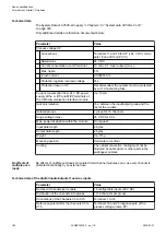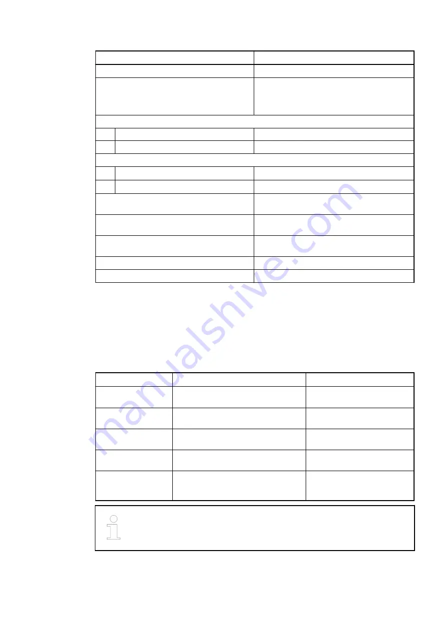
Parameter
Value
Number of channels per module
32
Distribution of the channels into groups
4 groups of 8 channels each (1.0...1.7,
2.0...2.7, 3.0...3.7, 4.0...4.7), the allocation of
the channels is given by the inserted I/O
module
Terminals 1.8...4.8 and 1.9...4.9
Max. voltage
30 V DC
Max. permitted total current
10 A
Terminals 1.0...1.7, 2.0...2.7, 3.0...3.7, 4.0...4.7
Max. voltage
300 V AC
1
)
Max. permitted current
3 A
2
)
Grounding
Direct connection to the grounded DIN rail or
via the screws with wall mounting
Screw terminals
Front terminal, conductor connection vertically
with respect to the printed circuit board
Spring terminals
Front terminal, conductor connection vertically
with respect to the printed circuit board
Weight
200 g
Mounting position
Horizontal or vertical
1
) Only when the voltage is not limited by the specification of the I/O channel or the supply input
which is internally connected to the terminal.
2
) The terminals are connected to the electronic module via internal connectors (X22 (or 3b),
X23 (or 3b), X32, X33 and X34). The current per terminal is limited by the permitted current of
these connectors.
1.5.4.2
Ordering data
Part no.
Description
Product life cycle phase *)
1SAP 217 200
R0001
TU531, terminal unit, 230 V AC,
relays, screw terminals
Active
1SAP 217 000
R0001
TU532, terminal unit, 230 V AC,
relays, spring terminals
Active
1SAP 417 000
R0001
TU532-XC, terminal unit, 230 V AC,
relays, spring terminals, XC version
Active
1SAP 215 100
R0001
TU532-H, terminal unit, hot swap,
230 V AC, relays, spring terminals
Active
1SAP 415 100
R0001
TU532-H-XC, terminal unit, hot swap,
230 V AC, relays, spring terminals, XC
version
Active
*) Modules in lifecycle Classic are available from stock but not recommended
for planning and commissioning of new installations.
Device specifications
Terminal units (AC500 standard) > TU531 and TU532 for I/O modules
2022/01/31
3ADR010278, 3, en_US
141


