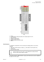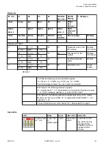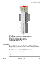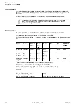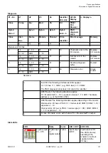
The inputs/outputs are group-wise galvanically isolated from each other.
All other circuitry of the module is galvanically isolated from the inputs/outputs.
Functionality
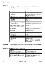
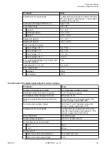
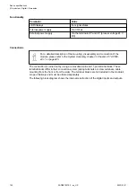
Parameter
Value
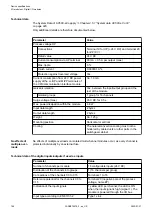
Digital inputs
Max. 16 (24 V DC), can be used as sink inputs
Digital outputs
Max. 16 (transistor outputs 24 V DC, max. 0.1 A)
LED displays
For signal states
Internal power supply
Via I/O bus
External power supply
Via the terminals ZP and UP (process voltage 24 V
DC)
Connections
For a detailed description of the mounting, disassembly and connection of the
module, please refer to the System Assembly chapter
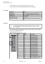
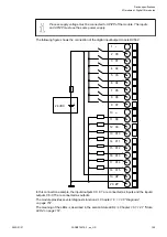
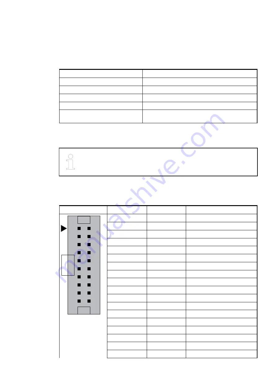
The connection is established out by using the 20-pin Interfast connector. For further informa-
tion, refer to the Interfast documentation.
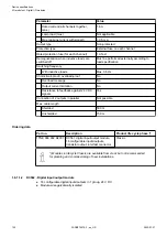
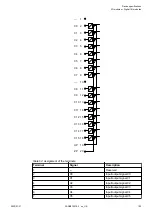
The assignment of the terminals:
Table 61: Assignment of the terminals for DC561
PIN
Signal
Description
1
C0
Input/output signal C0
2
C1
Input/output signal C1
3
C2
Input/output signal C2
4
C3
Input/output signal C3
5
C4
Input/output signal C4
6
C5
Input/output signal C5
7
C6
Input/output signal C6
8
C7
Input/output signal C7
9
C8
Input/output signal C8
10
C9
Input/output signal C9
11
C10
Input/output signal C10
12
C11
Input/output signal C11
13
C12
Input/output signal C12
14
C13
Input/output signal C13
15
C14
Input/output signal C14
16
C15
Input/output signal C15
17
UP
Process voltage UP +24 V DC
18
ZP
Process voltage ZP 0 V DC
Device specifications
I/O modules > Digital I/O modules
2022/01/31
3ADR010278, 3, en_US
144


