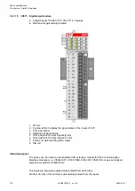
Functionality
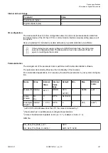
Parameter
Value
LED displays
For signal states
Internal power supply
Via I/O bus
External power supply
Not necessary
Connections
For a detailed description of the mounting, disassembly and connection of the
module, please refer to the System Assembly chapter
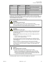
The connection is carried out by using removable 9-pin and 11-pin terminal blocks. These
terminal blocks differ in their connection system (spring terminals or screw terminals, cable
mounting from the front or from the side). The terminal blocks are not included in the module's
scope of delivery and must be ordered separately.
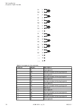
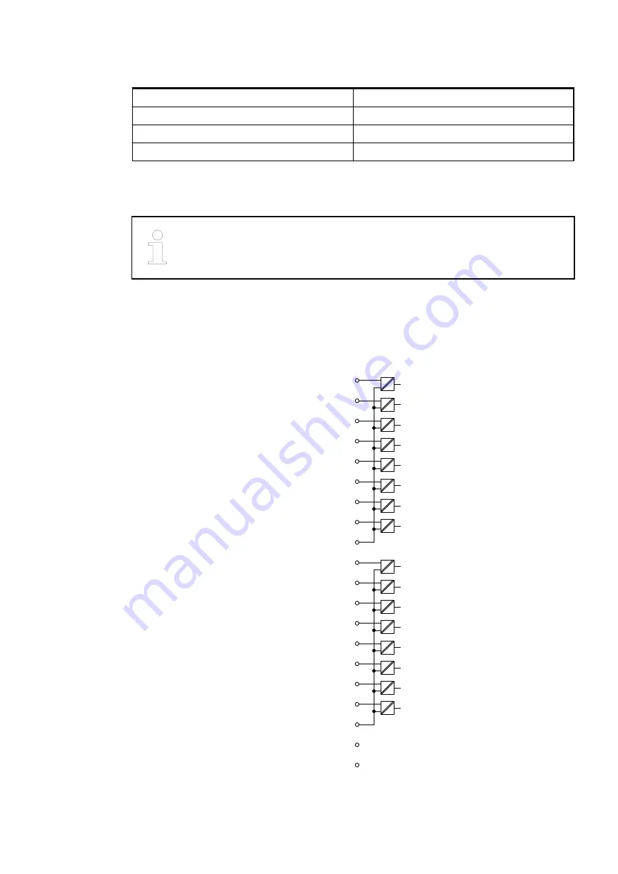
I1
2
I0
1
I3
4
I2
3
I5
6
I4
5
I7
8
I6
7
I9
11
I8
10
LI11
13
I10
12
I13
15
I12
14
I15
17
I14
16
N0..7 9
N8..15 18
---
19
---
20
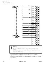
Fig. 6: Block diagram for the internal construction of the digital inputs.
Device specifications
I/O modules > Digital I/O modules
2022/01/31
3ADR010278, 3, en_US
186

