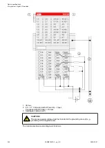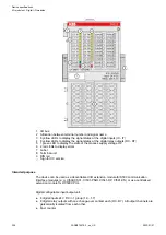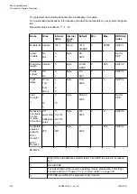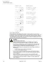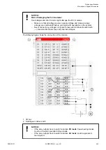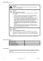
NOTICE!
Risk of damaging the PLC module!
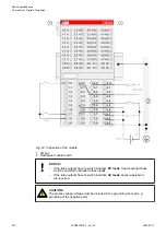
The following has to be considered when connecting input and output voltages
to the module:
–
All 230 V AC feeds must be single-phase from the same supply system.
–
Connection of 2 or more relay contacts in series is possible; however, vol-
tages above 230 V AC and 3-phase loads are not allowed.
–
The 8 change-over contacts of the relays are galvanically isolated from
channel to channel. This allows to connect loads of 24 V DC and 230 V AC
to relay outputs of the same module. In such cases it is necessary that both
supply voltages are grounded to prevent unsafe floating grounds.
NOTICE!
Risk of damaging the PLC module!
There is no internal short-circuit or overload protection for the relay outputs.
Protect the relay contacts by back-up fuses of 6 A max. (characteristic gG/gL).
Depending on the application, fuses can be used for single channels or module-
wise.
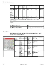
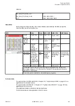
Internal data exchange
Without the fast counter
With the fast counter (only
with AC500)
Digital inputs (bytes)
1
3
Digital outputs (bytes)
1
3
Counter input data (words)
0
4
Counter output data (words)
0
8
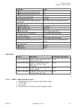
I/O configuration
The module itself does not store configuration data. It receives its parameterization data from
the master device of the I/O bus (CPU or communication interface module) during power-up of
the system.
Hence, replacing I/O modules is possible without any re-parameterization via software.
If the external power supply voltage via UP/ZP terminals fails, the I/O module
loses its configuration data. The whole station has to be switched off and on
again to re-configure the module.
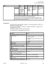
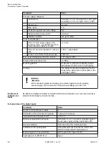
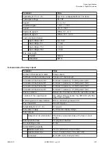
Parameterization
Firmware version
Configuration
Firmware version > V2.0.0
The arrangement of the parameter data is per-
formed by Control Builder Plus/ Automation
Builder software.
Device specifications
I/O modules > Digital I/O modules
2022/01/31
3ADR010278, 3, en_US
333

