I/O configuration
The configuration data of the onboard I/Os is stored in the processor modules PM50x2. See
PLC configuration:
Parameterization
For information about parameterization, refer to the description for onboard I/Os for processor
modules PM50x2. See PLC configuration: and
Diagnosis
No diagnosis is generated for the onboard I/O.
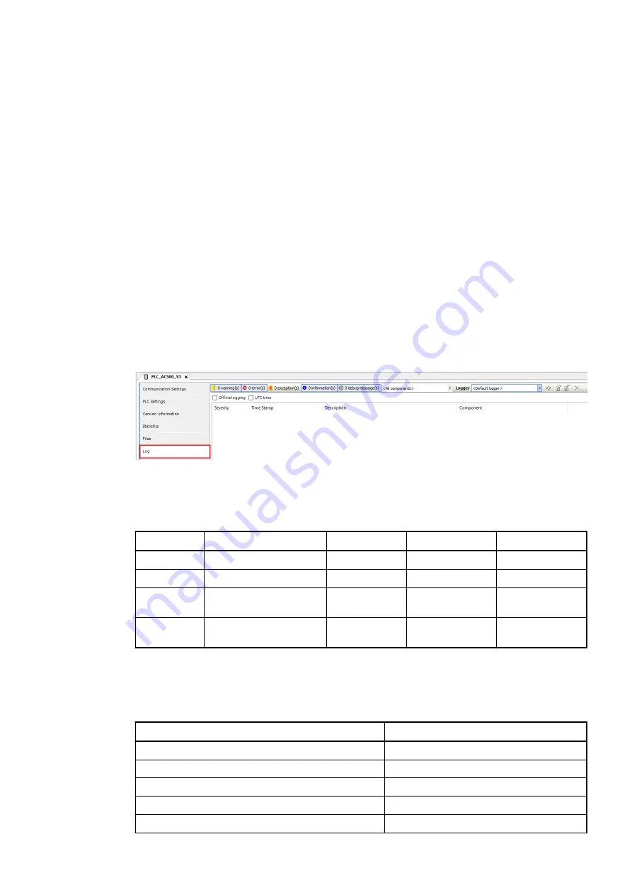
There is only an error message if the configuration does not work. A log entry is generated.
The Automation Builder already prevents faulty values from being entered in the configuration.
If the configuration does not work, there is a system error, if e.g. faulty software or wrong
versions are installed.
Otherwise there are error messages from the blocks for the individual functions.
Displays
Table 14: States of the I/Os
LED
Status
Color
LED = ON
LED = OFF
I
Digital input
yellow
Input is ON
Input is OFF
O
Digital transistor output
yellow
Output is ON
Output is OFF
NO
Digital relay output
yellow
Relay contact is
closed
Relay contact is
open
C
Digital configurable
input/output
yellow
Configured input/
output is ON
Configured input/
output is OFF
Technical data
Technical data of the digital inputs
Parameter
Value
Number of channels per module
12
Distribution of the channels into groups
1 group of 12 channels
Galvanic isolation
Yes, per group
Connections of the channels I0 to I11
Terminals 2 to 13
Reference potential for the channels I0 to I11
Terminal 1
Device specifications
Processor modules > AC500-eCo
2022/01/31
3ADR010278, 3, en_US
35


