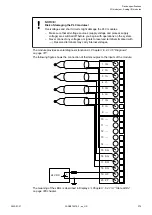
NOTICE!
Risk of damaging the PLC modules!
The PLC modules must not be removed while the plant is connected to a power
supply.
Make sure that all voltage sources (supply and process voltage) are switched
off before you
–
connect or disconnect any signal or terminal block
–
remove or replace a module.
NOTICE!
Risk of damaging the PLC modules!
Overvoltages and short circuits might damage the PLC modules.
–
Make sure that all voltage sources (supply voltage and process supply
voltage) are switched off before you begin with operations on the system.
–
Never connect any voltages or signals to reserved terminals (marked with
---). Reserved terminals may carry internal voltages.
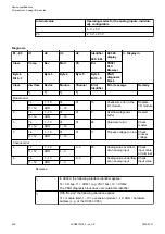
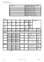
The module provides several diagnosis functions
Chapter 1.6.2.1.2.6 “Diagnosis”
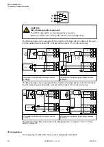
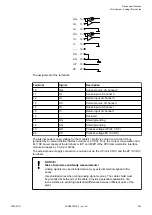
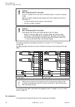
The following figures show the connection of RTDs to the inputs of the analog input module
AI562.
24 VDC
-
+
10
11
O0+
I0+
13 O1+
12 I0-
14 I1+
15 I1-
16 ---
17 SG
18 SG
19 UP
20 ZP
24 VDC
-
+
10
11
O0+
I0+
13 O1+
12 I0-
14 I1+
15 I1-
16 ---
17 SG
18 SG
19 UP
20 ZP
2-wires input
3-wires input
With 2-wires connection, the resistance of the connection wires influences the
accuracy of the measured value. Use 3-wires connection to achieve the guaran-
teed measuring accuracy.
The meaning of the LEDs is described in the Displays section
I/O configuration
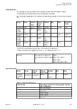
The analog input module AI562 does not store configuration data itself.
Device specifications
I/O modules > Analog I/O modules
2022/01/31
3ADR010278, 3, en_US
364

