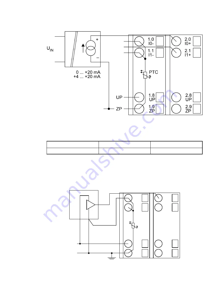
Connection of active-type analog sensors (Current) with galvanically isolated power supply
Fig. 28: Connection example
The following measuring ranges can be configured
Chapter 1.6.2.2.2.6 “Parameterization”
Chapter 1.6.2.2.2.9 “Measuring ranges” on page 449
Current
0 mA...20 mA
1 channel used
Current
4 mA...20 mA
1 channel used
The function of the LEDs is described under Displays
Chapter 1.6.2.2.2.7 “Diagnosis”
Unused input channels can be left open-circuited, because they are of low resistance.
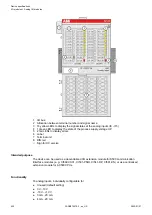
Connection of active-type analog sensors (Voltage) with no galvanically isolated power supply
UP
ZP
1.0
I0-
1.1
I1-
1.8
UP
1.9
ZP
PTC
2.0
I0+
2.1
I1+
2.8
UP
2.9
ZP
0 ... 10 V
AGND
Fig. 29: Connection example
Device specifications
I/O modules > Analog I/O modules
2022/01/31
3ADR010278, 3, en_US
440


