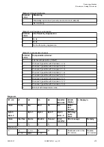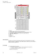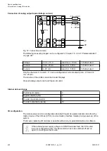
E1...E4
d1
d2
d3
d4
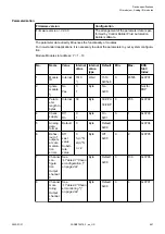
Identifier
000...063
AC500
display
<− Display in
Class
Comp
Dev
Mod
Ch
Err
PS501
PLC
browser
Byte 6
Bit 6...7
-
Byte 3
Byte 4
Byte 5
Byte 6
Bit 0...5
FBP diag-
nosis
block
Class
Interface
Device
Module
Channel
Error
identifier
Error message
Remedy
1
)
2
)
3
)
4
)
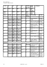
4
14
1...10
1
0...7
2
Invalid measured value
of the channel caused
by overly high voltage
difference
Check
voltage dif-
ference;
install
equalizing
conductors
if neces-
sary
11 / 12
ADR
1...10
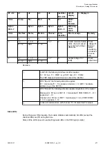
4
14
1...10
1
0...7
11
Output voltage 10 V
faulty
Check
output load
11 / 12
ADR
1...10
Remarks:
1
)
In AC500, the following interface identifier applies:
14 = I/O bus, 11 = COM1 (e.g. CS31 bus), 12 = COM2.
The FBP diagnosis block does not contain this identifier.
2
)
With "Device" the following allocation applies:
31 = module itself, 1...10 expansion module 1...10, ADR = hardware
address (e.g. of the DC551)
3
)
With "Module" the following allocation applies dependent of the master:
Module error: I/O bus or FBP: 31 = module itself; COM1/COM2: 1...10 =
expansion 1...10
Channel error: I/O bus or FBP = module type (1 = AI); COM1/COM2:
1...10 = expansion 1...10
4
)
In case of module errors, with channel "31 = Module itself" is output.
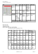
State LEDs
During the power ON procedure, the module initializes automatically. All LEDs (except the
channel LEDs) are ON during this time.
States of the LEDs (see also section Diagnosis LEDs in the S500 system data):
Device specifications
I/O modules > Analog I/O modules
2022/01/31
3ADR010278, 3, en_US
477

