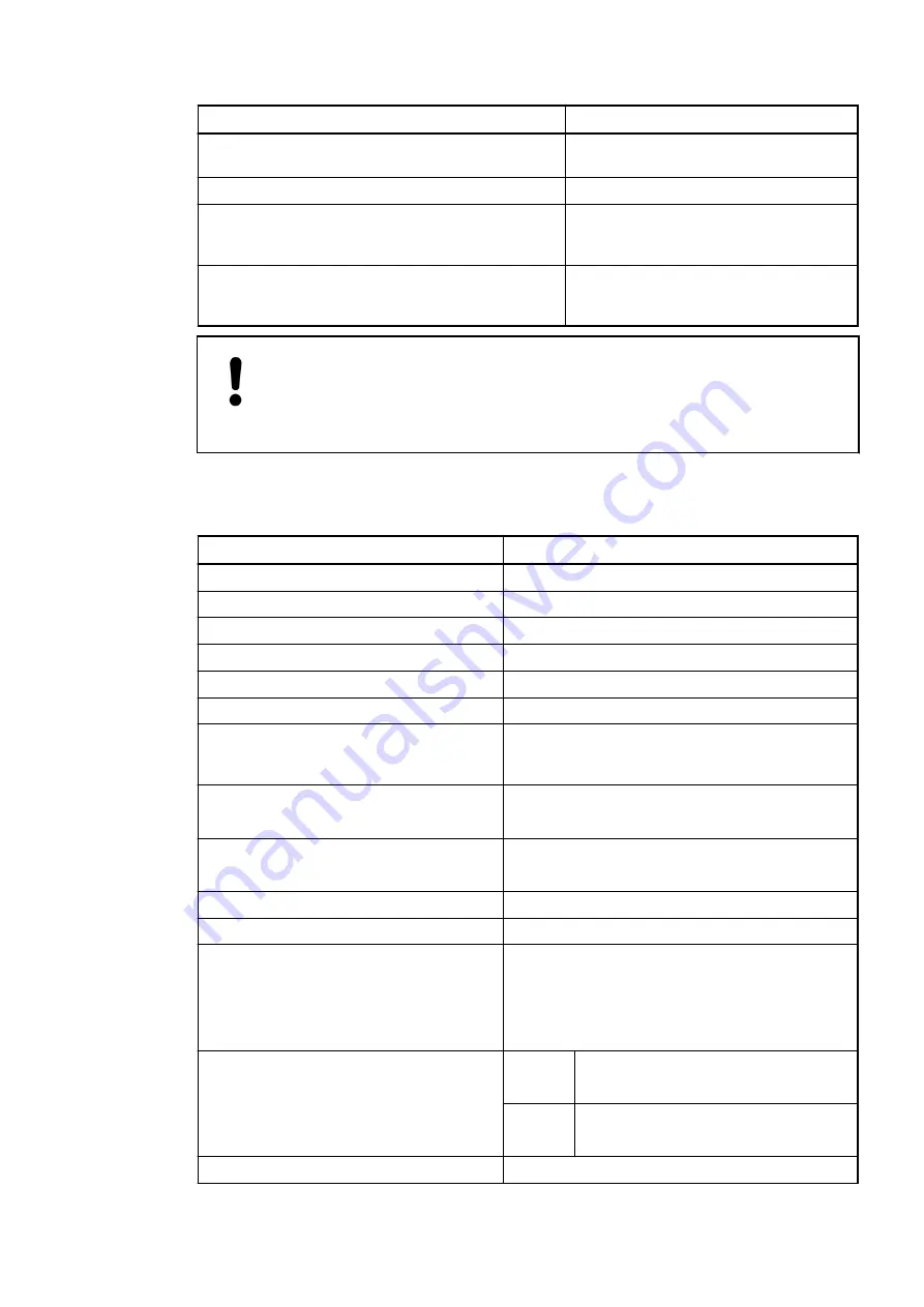
Parameter
Value
Max. length of analog cables, conductor cross sec-
tion > 0.14 mm²
100 m
Weight
300 g
Mounting position
Horizontal or vertical with derating
(output load reduced to 50 % at 40 °C
per group)
Cooling
The natural convection cooling must not
be hindered by cable ducts or other parts
in the switchgear cabinet.
NOTICE!
Attention:
All I/O channels (digital and analog) are protected against reverse polarity,
reverse supply, short circuit and continuous overvoltage up to 30 V DC.
Technical data of the analog inputs
Parameter
Value
Number of channels per module
8
Distribution of channels into groups
1 group of 8 channels
Connections of the channels I0- to I7-
Terminals 1.0 to 1.7
Connections of the channels I0+ to I7+
Terminals 2.0 to 2.3
Input type
Bipolar (not with current or Pt100/Pt1000/Ni1000)
Galvanic isolation
Against internal supply and other modules
Configurability
0 V...10 V, -10 V...+10 V, 0 mA...20 mA,
4 mA...20 mA, Pt100/1000, Ni1000 (each input
can be configured individually)
Channel input resistance
Voltage: > 100 k
W
Current: ca. 330
W
Time constant of the input filter
Voltage: 100
µ
s
current: 100
µ
s
Indication of the input signals
One LED per channel
Conversion cycle
2 ms (for 8 8 outputs), with Pt/Ni... 1 s
Resolution
Range 0 V...10 V: 12 bits
Range -10 V...+10 V: 12 bits + sign
Range 0 mA...20 mA: 12 bits
Range 4 mA...20 mA: 12 bits
Conversion error of the analog values
caused by non-linearity, adjustment error
at factory and resolution within the normal
range
Typ.
±
0.5 % of full scale
at 25 °C
Max.
±
1 % of full scale (all ranges)
at 0 °C...60 °C or EMC disturbance
Unused voltage inputs
Are configured as "unused"
Device specifications
I/O modules > Analog I/O modules
2022/01/31
3ADR010278, 3, en_US
546

