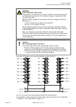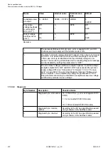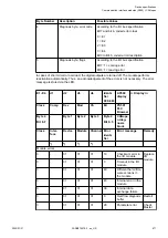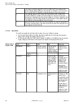
E1..E4
d1
d2
d3
d4
Identi-
fier
000..063
AC500
display
<− Display in
Class
Comp
Dev
Mod
Ch
Err
PS501
PLC
Browser
Byte 4
Bit 6..7
-
Byte 1
Byte 2
Byte 3
Byte 4
Bit 0..5
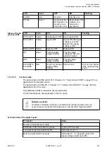
CANope
n diag-
nosis
block
Class
Inter-
face
Device
Module
Channel Error
identi-
fier
Error message
Remedy
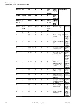
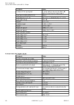
1
)
2
)
3
)
4
)
4
-
31
31
31
10
Voltage overflow
on outputs (above
UP3 level)
5
)
Check
termi-
nals/
check
process
supply
voltage
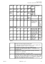
Channel error digital
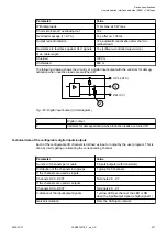
4
-
31
2
8...15
46
Externally voltage
detected at digital
output DO0..DO7
6
)
Check
terminals
4
-
31
4
0...7
46
Externally voltage
detected at digital
output DC0..DC7
6
)
Check
terminals
4
-
31
4
0...7
47
Short circuit at
digital output
DC0..DC7
7
)
Check
terminals
4
-
31
2
8...15
47
Short circuit at
digital output
DO0..DO7
7
)
Check
terminals
Remarks:
1
)
In AC500, the following interface identifier applies:
"-" = Diagnosis via bus-specific function blocks; 0 ... 4 or 10 = position of the
communication module;14 = I/O bus; 31 = module itself
The identifier is not contained in the CI542-DP diagnosis block.
2
)
With "Device" the following allocation applies: 31 = module itself, 1..10 =
expansion module
3
)
With "Module" the following allocation applies depending on the master:
Module error: 31 = module itself
Channel error: module type (1 = AI, 2 = DO, 3 = AO)
4
)
This message appears if external voltages at one or more terminals DC0..DC7
or DO0..DO7 cause other digital outputs to be supplied by that voltage (voltage
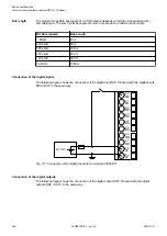
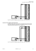
Chapter 1.7.2.3.3 “Connections” on page 660
All outputs of the digital output groups will be turned off for 5 seconds. The
diagnosis message appears for the whole output group.
Device specifications
Communication interface modules (S500) > CANopen
2022/01/31
3ADR010278, 3, en_US
673


