5
)
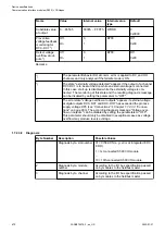
The voltage at digital outputs DC0..DC7 and DO0..DO7 has exceeded the
process supply voltage UP3 (see 'Connections'
). A diagnosis message appears for the whole module.
6
)
This message appears if the output of a channel DC0..DC7 or DO0..DO7
should be switched on while an external voltage is connected. In this case
the start-up is disabled while the external voltage is connected. Otherwise, this
could produce reverse voltage flowing from this output to other digital outputs.
This diagnosis message appears for each channel.
7
)
Short circuit: After a short circuit has been detected, the output is deactivated
for 100ms. Subsequently, a new start-up will be executed. This diagnosis mes-
sage appears for each channel.
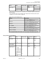
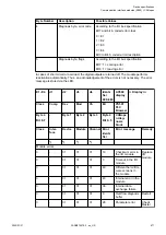
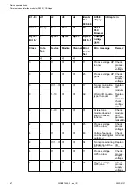
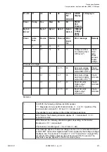
1.7.2.3.9 State LEDs
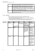
The LEDs are located at the front of the module. There are 2 different groups:
● The 5 system LEDs (PWR, CN-RUN, CN-ERR, S-ERR and I/O bus) show the operation
states of the module and display possible errors.
● The 29 process LEDs (UP, UP3, inputs, outputs, CH-ERR1 to CH-ERR3) show the process
supply voltage and the states of the inputs and outputs and display possible errors.
LED
Color
OFF
ON
Flashing
PWR/RUN
Green
Process supply
voltage missing
Internal supply
voltage OK,
module ready for
communication
with I/O controller
Start-up / pre-
paring communi-
cation
Yellow
---
---
---
CN-RUN
Green
---
Device config-
ured, CANopen
bus in OPERA-
TIONAL state
and cyclic data
exchange run-
ning
Flashing:
CANopen bus in
PRE-OPERA-
TIONAL state
and slave is
being configured
Single flash:
CANopen bus in
STOPPED state.
Flickering: Auto-
detect is active
CN-ERR
Red
No system error
CANopen Bus is
OFF
Flashing: Config-
uration error
Single flash: error
counter overflow
due to too many
error frames
Double flash: A
node-guard or a
heartbeat event
occurred
Flickering: Auto-
detect is active
States of the 5
system LEDs
Device specifications
Communication interface modules (S500) > CANopen
2022/01/31
3ADR010278, 3, en_US
674


