3
)
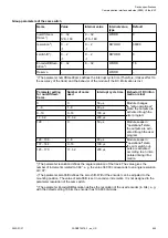
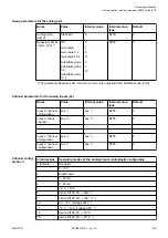
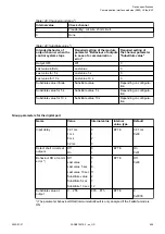
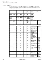
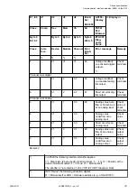
With "Module" the following allocation applies dependent of the master:
31 = Module itself (Module error) or Module type (1=AI, 2=DO, 3=AO; channel
error)
4
)
Diagnosis message appears for the whole output group and not per channel.
The message occurs if the output channel is already active.
5
)
Diagnosis message appears per channel. The message occurs if the output
channel is not active.
1.7.3.1.9 State LEDs
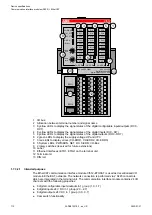
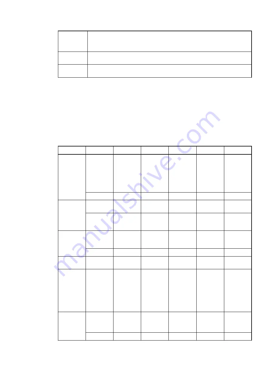
The LEDs are located at the front of module. There are 2 different groups:
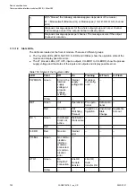
● The 5 system LEDs (PWR, NET, DC, S-ERR and I/O-Bus) show the operation state of the
module and display possible errors.
● The 27 process LEDs (UP, UP3, inputs, outputs, CH-ERR1 to CH-ERR3) show the process
supply voltage and the states of the inputs and outputs and display possible errors.
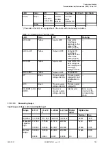
Table 150: States of the 5 system LEDs
LED
Color
Off
On
Flashing
1x Flash
2x Flash
PWR/RUN
Green
Error in the
internal
supply
voltage or
process
voltage
missing
Internal
supply
voltage OK
Module is
not config-
ured
--
--
Yellow
--
--
--
--
--
NET
Green
Init
Operational Pre-opera-
tional
Safe-opera-
tional
--
Red
No error
PDI
Watchdog
Timeout
Invalid Con-
figuration
Unsolicited
State
Change
Application
time out
DC *)
Green
Distributed
Clock not
active
Distributed
Clock active
--
--
--
Red
--
--
--
--
--
S-ERR
Red
No error
Internal
error
--
--
--
I/O-Bus
Green
No commu-
nication
interface
modules
connected
or commu-
nication
error
---
---
--
--
ETH1
Green
No
EtherCAT
connection
Link OK
No data
transfer
Link OK
Data
transfer OK
--
--
Yellow
--
--
--
--
--
Device specifications
Communication interface modules (S500) > EtherCAT
2022/01/31
3ADR010278, 3, en_US
702

