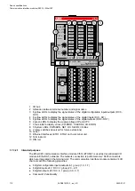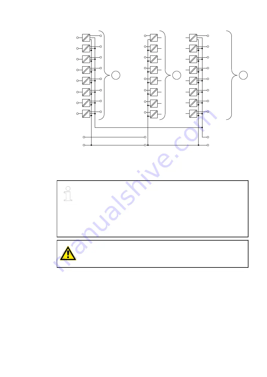
3.0 DO 8
3.1 DO 9
3.2 DO 10
3.3 DO 11
3.4 DO 12
3.5 DO 13
3.6 DO 14
3.7 DO 15
DI 8 2.0
DI 9 2.1
DI 10 2.2
DI 11 2.3
DI 12 2.4
DI 13 2.5
DI 14 2.6
DI 15 2.7
1.8
1.9
UP +24 V
ZP 0 V
2.8
2.9
3.9
3.8
UP3 +24 V
ZP 0 V
2
3
DC 0 1.0
DC 1 1.1
DC 2 1.2
DC 3 1.3
DC 4 1.4
DC 5 1.5
DC 6 1.6
DC 7 1.7
1
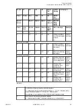
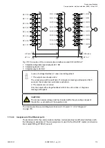
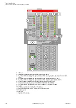
Fig. 133: Connection of the communication interface module CI512-ETHCAT
1
8 digital configurable inputs/outputs 24 V DC
2
8 digital inputs 24 V DC
3
8 digital outputs 24 V DC
In case of voltage feedback, 2 cases are distinguished:
1. The outputs are already active
The output group will be switched off. A diagnosis message will appear. After 5
seconds, the module tries automatic reactivation.
2. The outputs are not active
Only the output with voltage feedback will not be set to active. A diagnosis
message will appear.
CAUTION!
The process supply voltage must be included within the grounding concept of
the plant (e. g. grounding of the negative pole).
The module provides several diagnosis functions
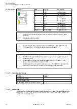
1.7.3.2.4 Assignment of the Ethernet ports
The terminal unit for the communication interface module provides two Ethernet interfaces with
the following pin assignment. The pin assignment is used for the EtherCAT master (communica-
tion module CM5xy-ETHCAT) as well.
Device specifications
Communication interface modules (S500) > EtherCAT
2022/01/31
3ADR010278, 3, en_US
715

