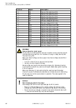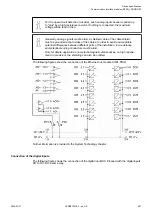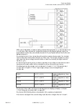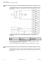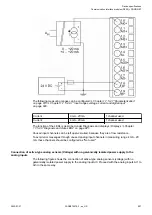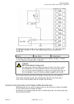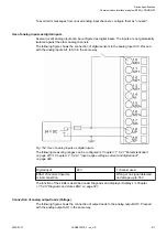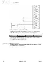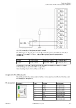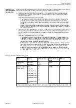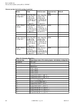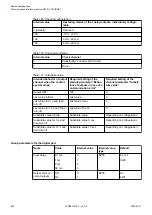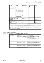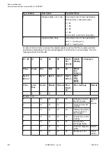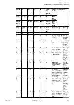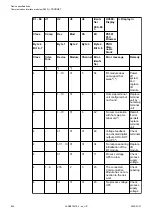
The following measuring ranges can be configured
Chapter 1.7.5.2.7 “Parameterization”
Chapter 1.7.5.2.9.1 “Input ranges voltage, current and digital input”
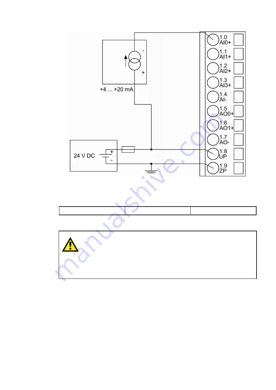
Current
4 mA...20 mA
1 channel used
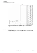
The function of the LEDs is described under Diagnosis and displays / Displays
1.7.5.2.8 “Diagnosis and state LEDs” on page 821
.
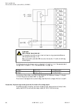
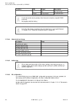
CAUTION!
Risk of overloading the analog input!
If an analog current sensor supplies more than 25 mA for more than 1 second
during initialization, this input is switched off by the module (input protection).
Use only sensors with fast initialization or without current peaks higher than 25
mA. If not possible, connect a 10-volt zener diode in parallel to AIx+ and ZP.
Unused input channels can be left open-circuited, because they are of low resistance.
To avoid error messages through unused analog input channels in measuring range
4 mA...20 mA, these channels should be configured as "Not used".
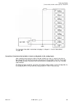
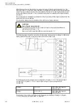
Connection of active-type analog sensors (Voltage) to differential analog inputs
Differential inputs are very useful, if analog sensors are used which are remotely non-isolated
(e.g. the minus terminal is remotely grounded).
The evaluation using differential inputs helps to considerably increase the measuring accuracy
and to avoid ground loops.
Device specifications
Communication interface modules (S500) > PROFINET
2022/01/31
3ADR010278, 3, en_US
809


