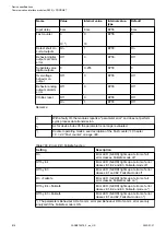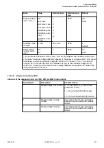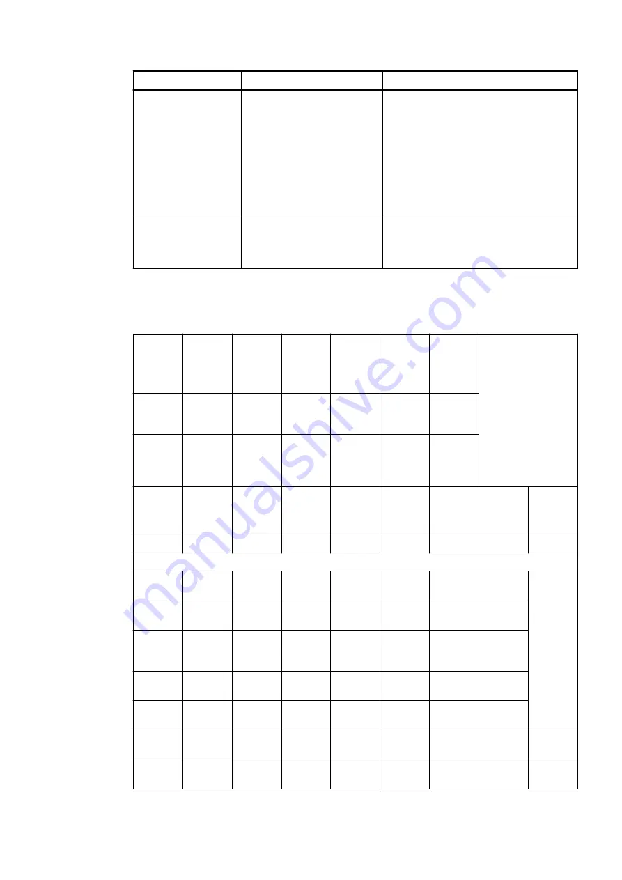
Byte Number
Description
Possible Values
4
Diagnosis Byte, error code
According to the I/O bus specification
Bit 7 and bit 6, coded error class
0 = E1
1 = E2
2 = E3
3 = E4
Bit 0 to bit 5, coded error description
5
Diagnosis Byte, flags
According to the I/O bus specification
Bit 7: 1 = coming error
Bit 6: 1 = leaving error
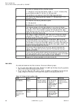
In cases of short circuit or overload, the digital outputs are turned off. The modules performs
reactivation automatically. Thus an acknowledgement of the errors is not necessary. The error
message is stored via the LED.
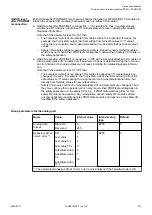
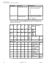
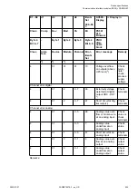
E1...E4
d1
d2
d3
d4
Identi-
fier
000...06
3
AC500-
Display
<− Display in
Class
Comp
Dev
Mod
Ch
Err
PS501
PLC
Browser
Byte 4
Bit 6...7
-
Byte 1
Byte 2
Byte 3
Byte 4
Bit 0...5
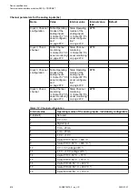
PNIO
diag-
nosis
block
Class
Inter-
face
Device
Module
Channel Error-
Identi-
fier
Error message
Remedy
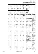
1
)
2
)
3
)
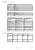
Module errors
3
-
31
31
31
19
Checksum error in
the I/O module
Replace
I/O
module
3
-
31
31
31
3
Timeout in the I/O
module
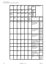
3
-
31
31
31
40
Different hard-/firm-
ware versions in
the module
3
-
31
31
31
43
Internal error in the
module
3
-
31
31
31
36
Internal data
exchange failure
3
-
31
31
31
9
Overflow diagnosis
buffer
Restart
3
-
31
31
31
26
Parameter error
Check
master
Device specifications
Communication interface modules (S500) > PROFINET
2022/01/31
3ADR010278, 3, en_US
822

