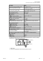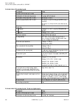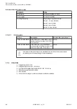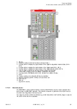
Connection of the configurable digital inputs/outputs
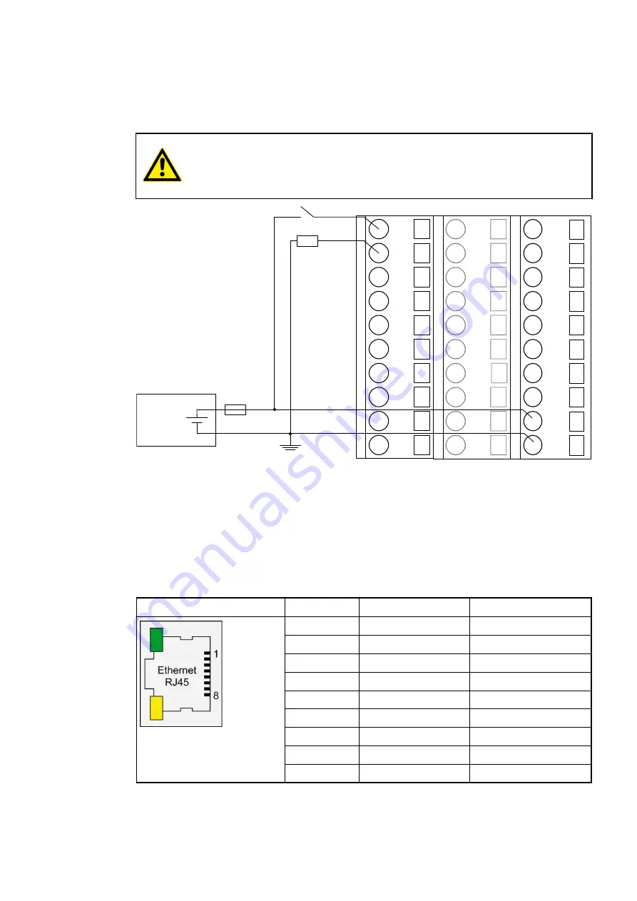
The following figure shows the connection of the configurable digital input/output DC0 and
DC1. DC0 is connected as an input and DC1 is connected as an output. Proceed with the
configurable digital inputs/outputs DC2 to DC7 in the same way.
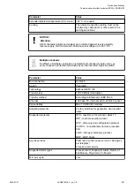
CAUTION!
If a DC channel is used as input, the source for the input signals should be the
Chapter 1.7.5.3.3 “Connections” on page 838
.
1.0
DC0
1.1
DC1
1.2
DC2
1.3
DC3
1.4
DC4
1.5
DC5
1.6
DC6
1.7
DC7
1.8
UP
1.9
ZP
-
+
24 V DC
2.4
DI14
2.0
DI8
2.1
DI9
2.2
DI10
2.3
DI11
DI12
2.5
DI13
2.6
2.7
DI15
2.8
UP
2.9
ZP
3.0
DO8
3.1
DO9
3.2
DO10
3.3
DO11
3.4
DO12
3.5
DO13
3.6
DO14
3.7
DO15
3.8
UP3
3.9
ZP
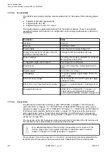
The meaning of the LEDs is described in Displays
Chapter 1.7.5.3.8.1 “State LEDs”
Assignment of the Ethernet ports
The terminal unit for the communication interface module provides two Ethernet interfaces with
the following pin assignment:
Interface
PIN
Signal
Description
1
TxD+
Transmit data +
2
TxD-
Transmit data -
3
RxD+
Receive data +
4
NC
Not connected
5
NC
Not connected
6
RxD-
Receive data -
7
NC
Not connected
8
NC
Not connected
Shield
Cable shield
Functional earth
Pin assignment
Device specifications
Communication interface modules (S500) > PROFINET
2022/01/31
3ADR010278, 3, en_US
844

