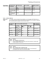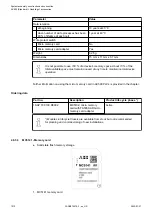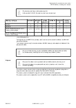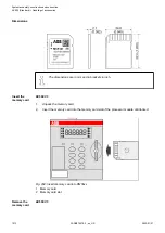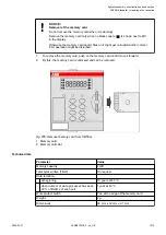
Pairs
EIA/TIA 568
Version 1
EIA/TIA 568
Version 2
DIN 47100
IEC 189.2
Pair 3
white/
green
green
blue
orange
grey
pink
white
green
Pair 4
white/
brown
brown
brown
slate
blue
red
white
brown
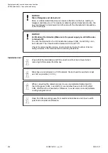
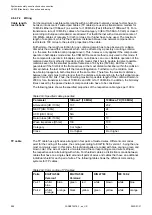
Two general variants are distinguished for the pin assignment of the normally used RJ45
connectors: EIA/TIA 568 version A and version B. The wiring according to EIA/TIA 568 version
B is the one most commonly used.
T568A
T3
1
R3
2
T2
3
R1
4
T1
5
R2
6
T4
7
R4
8
Pair 3
Pair 4
Pair 1
Pair 2
T568B
T3
1
R3
2
T2
3
R1
4
T1
5
R2
6
T4
7
R4
8
Pair 2
Pair 4
Pair 1
Pair 3
Fig. 197: Pin assignment of RJ45 sockets
2.6.4.7.3 Cable types
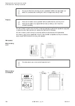
Particular use
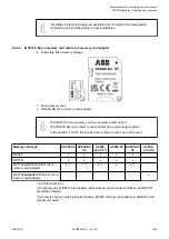
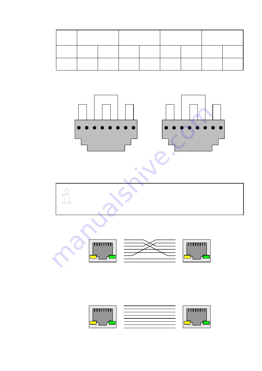
Crossover cables are needed only for a direct Ethernet connection without
crossover functionality. In particular for AC500 modules in product life cycle
phase "Classic".
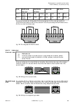
Crossover cables are for a direct Ethernet connection of two terminal devices as the simplest
variant of a network. From transmission lines of the first station to the reception lines of the
second station.
12345678
12345678
1
2
3
4
5
6
7
8
1
2
3
4
5
6
7
8
Fig. 198: Wiring of a crossover cable
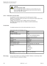
For networks with more than two subscribers, hubs or switches have to be used additionally for
distribution. These active devices already have the crossover functionality implemented which
allows a direct connection of the terminal devices using straight-through cables.
12345678
12345678
1
2
3
4
5
6
7
8
1
2
3
4
5
6
7
8
Fig. 199: Wiring of a straight-through cable
Crossover cable
Straight-through
cable
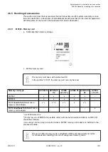
System assembly, construction and connection
AC500 (Standard) > Connection and wiring
2022/01/31
3ADR010278, 3, en_US
999


