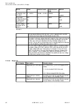
Parameter
Value
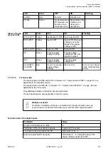
Inputs and outputs
8 digital inputs (24 V DC)
8 digital transistor outputs (24 V DC, 0.5 A
max.)
8 configurable digital inputs/outputs (24 V DC,
0.5 A max.)
1.7.2.3.3 Connections
The CANopen communication interface module is plugged on the I/O terminal units TU517
Chapter 1.5.3 “TU517 and TU518 for communication interface modules” on page 132
or
Chapter 1.5.3 “TU517 and TU518 for communication interface modules” on page 132
and accordingly TU509 or TU510. Properly position the module and press until it locks in place.
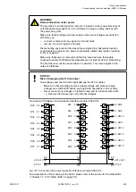
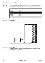
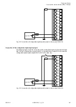
The connection of the I/O channels is established using the 30 terminals of the I/O terminal unit.
I/O modules can be replaced without re-wiring the terminal units.
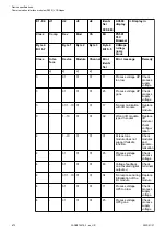
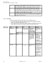
The terminals 2.8, 3.8, 2.9, 3.9 and 4.9 are electrically interconnected within the terminal unit
and always have the same assignment, irrespective of the inserted module:
Terminals 2.8 and 3.8: process supply voltage UP = +24 V DC
Terminal 4.8: process supply voltage UP3 = +24 V DC
Terminals 2.9, 3.9 and 4.9: process supply voltage ZP = 0 V
For a detailed description of the mounting, disassembly and connection of the
module, please refer to the System Assembly, Construction and Connection
Chapter 2.6 “AC500 (Standard)” on page 971.
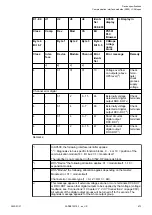
With a separate UP3 power supply, the digital outputs can be switched off
externally. This way, an emergency-off functionality can be realized.
Possibilities of connection
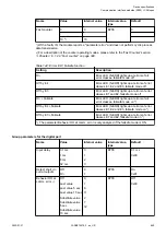
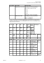
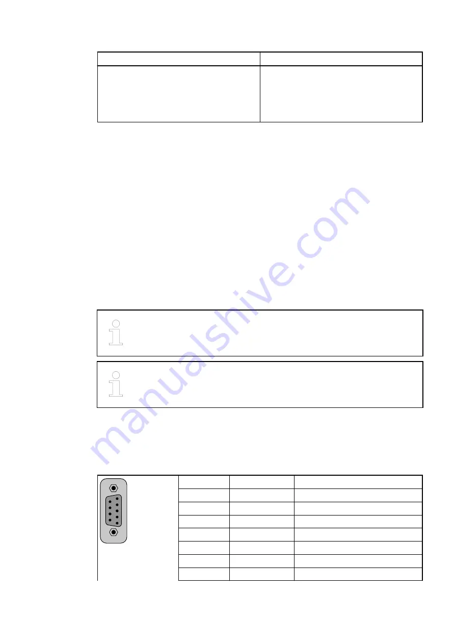
The assignment of the 9-pin female D-sub for the CANopen signals
1
5
6
9
1
---
Reserved
2
CAN-
Inverted signal of the CAN bus
3
CAN_GND
Ground potential of the CAN bus
4
---
Reserved
5
---
Reserved
6
---
Reserved
7
CAN+
Non-inverted signal of the CAN bus
8
---
Reserved
CI582-CN: Input/
Output charac-
teristics
Mounting on ter-
minal units
TU509 or TU510
Device specifications
Communication interface modules (S500) > CANopen
2022/01/31
3ADR010278, 3, en_US
660


