background image

Technical Data   4-3

MN796SUP

4.4  Dimensional Reference

The following tables contain dimensional references that identify the dimensional information applying to a given type code.

4.4.1  480V Drive with Disconnect

HP

Type Code

AMP

Base

Drive

Frame

UL Type /

NEMA 1

Dim. Ref.

(+B055)

UL Type /

NEMA 12

Dim. Ref.

250

ACB530-PC-316A-4

316

R8

PX1-8

PX12-8

300

ACB530-PC-368A-4

368

R8

PX1-8

PX12-8

350

ACB530-PC-414A-4

414

R8

PX1-8

PX12-8

400

ACB530-PC-486A-4

486

R8

PX1-8

PX12-8

450

ACB530-PC-526A-4

526

R8

PX1-8

PX12-8

500

ACB530-PC-602A-4

602

R8

PX1-8

PX12-8

550

ACB530-PC-645A-4

645

R8

PX1-8

PX12-8

4.5  Dimensions and Weights

Dimensions: ACB530-Px UL Type / NEMA 1

Dimension

Reference

UL Type / NEMA 1

Mounting Dimensions

mm

[inches]

UL Type / NEMA 1

Dimensions and Weights

mm kg

[inches] [lbs]

H1

W1

Mouting

Hardware

Height

(H)

Weight

(W)

Depth

(D)

Weight

Dimension

Drawing

PX1-8

1

Free Standing

Ø16

[Ø0.63]

2125

[83.7]

806

[31.7]

659

[25.9]

360

[794]

3AUA000021152

Sheet 1

1.

 See Section 4.5.4, UL Type / NEMA 1 & 12 - Floor Mount Enclosure Mounting Dimensions for mounting dimension details and 

additional free space recommendations.


Summary of Contents for ACB530 Series

Page 1: ...11 14 Installation Operating Manual MN796SUP ACB530 PC Packaged Drive with Disconnect Supplement to MN796 ACB530 User s Manual ...

Page 2: ...n download the latest version of this manual in Adobe Acrobat PDF format ACB530 Drive Manuals GENERAL MANUALS MN796 ACB5300 U1 User s Manual 1 200 HP Safety Installation Start Up Embedded Fieldbus Fieldbus Adapter Diagnostics Maintenance Technical Data MN796SUP ACB530 PC Packaged Drive with Disconnect Supplement for MN796 ACB530 U1 User s Manual Safety Installation Start Up Maintenance Technical D...

Page 3: ...ntenance Intervals 3 1 3 1 2 Drive Module Fan Replacement 3 1 3 1 3 Enclosure Fan Replacement UL Type NEMA 12 Floor Mount Enclosures 3 1 3 1 4 Floor Mount UL type NEMA 12 Filter Material 3 3 3 1 5 Floor Mount UL type NEMA 12 Enclosure Inlet Air Filter 3 3 Chapter 4 Technical Data 4 1 Ratings 4 1 4 1 1 Ratings 480 Volt Drives 4 1 4 2 Input Power Connections 4 1 4 2 1 Fuses 4 1 4 2 3 Drive s Power C...

Page 4: ...ii MN796SUP ...

Page 5: ... Safety Related to Installation and Maintenance These warnings are intended for anyone who works on the drive power cables or motor 1 4 1 Electrical Safety WARNING The ACB530 adjustable speed AC drive with Input Disconnect should ONLY be installed by a qualified electrician WARNING Even when the motor is stopped dangerous voltage is present at the Power Circuit terminals U1 V1 W1 and U2 V2 W2 and ...

Page 6: ...1 2 Introduction MN796SUP ...

Page 7: ...e Failure to disconnect power may cause serious injury or death 2 1 1 Application This manual contains supplemental information that is unique to ACB530 input disconnect configurations PC Refer to the base manual MN796 the ACB530 U1 User s Manual for all other information 2 1 2 Input Disconnect Features and Functions The ACB530 with Input Disconnect is an ACB530 AC adjustable frequency drive packa...

Page 8: ...2 2 Installation MN796SUP The following figure shows the front view of the ACB530 Drive with Input Disconnect standard configurations and identify the major components ...

Page 9: ...o MN796 the ACB530 U1 User s Manual Installation section Additional Reference in this Manual PREPARE for installation Preparing for Installation R8 Lifting the Drive Drive Identification Suitable Mounting Location PREPARE the Mounting Location Prepare the Mounting Location R8 Prepare the Mounting Location R8 Dimensions and Weights REMOVE the front cover Remove Front Cover R8 Remove Side Panel R8 U...

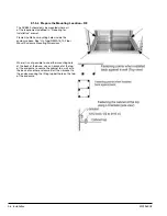
Page 10: ... the installation site 2 Remove the cabinet side panels from UL Type NEMA 1 and 12 enclosures for access to the cabinet pallet mounting bolts 6 torx screws hold each cabinet side panel in place Leave the side panels off until later 3 Remove the 4 bolts that secure the cabinet to the shipping pallet Warning Use the lifting lugs bars at the top of the unit to lift R8 drives 4 Use a hoist to lift the...

Page 11: ...12 B055 Voltage rating Ratings and Frame Size Charts in the Ratings sections of MN796 the ACB530 U1 User s Manual and this manual list technical specifications and identify the drive s frame size NOTE Some instructions in this document vary depending on the drive s frame size To read the Ratings table you need the Output current rating entry from the type code see above 2 1 4 3 Suitable Mounting L...

Page 12: ...as mounting holes inside the enclosure base See UL Type NEMA 1 12 Floor Mount Enclosure Mounting Dimensions Where it is not possible to use either mounting hole at the back of the base use an L bracket at the top of the enclosure to secure the cabinet to a wall or to the back of another enclosure Bolt the L bracket to the enclosure using the lifting lug bolt hole on the top of the enclosure ...

Page 13: ...emove the part If that is not practical cover nearby electrical components to protect them from all shavings or debris Do not connect or disconnect input or output power wiring or control wires when power is applied Never connect line voltage to drive output Terminals T1 T2 and T3 Do not make any voltage tolerance tests Hi Pot or Megger on any part of the unit Disconnect motor wires before taking ...

Page 14: ...s Connect input power to the terminals of the disconnect switch or circuit breaker Connect the equipment grounding conductor to the ground lug The figure below shows the connection points for Standard Drive with Input Disconnect configurations WARNING Check the motor and motor wiring insulation before connecting the ACB530 to line power Follow the procedure in MN796 the ACB530 U1 User s Manual Bef...

Page 15: ...ix years See Maintenance in MN796 the ACB530 U1 User s Manual Replace enclosure fan s NEMA 12 Every three years See Enclosure Fan Replacement UL Type NEMA 12 Floor Mount Enclosures For other frame sizes see Maintenance in MN796 the ACB530 U1 User s Manual Replace battery in the Assistant control panel All Every ten years See Maintenance in MN796 the ACB530 U1 User s Manual 3 1 2 Drive Module Fan R...

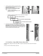
Page 16: ... Disconnect the fan s electrical connector from the cabinet roof top right Inside the cabinet 3 Undo the four fastening screws at the corners of the fan frame The screws are through bolts with nuts on the inside of the cabinet Do not drop the hardware into the drive 4 Remove the fan and fan frame as one unit 5 Disconnect the fan wiring and capacitor from the fan frame Then remove the four screws a...

Page 17: ...ust face the inside of the cabinet 3 1 5 Floor Mount UL Type NEMA 12 Enclosure Inlet Air Filter The inlet air filter for the R8 UL Type NEMA 12 enclosure is located in the enclosure front door 1 While holding the top of the filter frame pull up on the bottom of the frame The filter frame will slide up approximately 3 4 inch and can then safely removed by tilting away from the cabinet and lifting u...

Page 18: ... by to the right 5 Install the filter frame back to the cabinet door Carefully align the mounting hooks to the slots in the cabinet door The hooks should be pointing down Press in at the center of the filter frame with your knee and gently press down with your hands at the top of the frame The filter frame will slide down approximately inch and should be sealed securely to the door around the enti...

Page 19: ...ust face to outside of the cabinet and the colored side faces in Be sure to tuck the filter edges into the groove around the entire filter frame This detail is very important for proper operation 5 Reinstall the filter restrainers Insert the base of a retainer bottom of U shape into a filter frame channel Squeeze the open end of the U until it clears the filter frame Seat the open end of the U in ...

Page 20: ...3 6 Maintenance MN796SUP ...

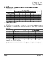
Page 21: ...are similar in functional characteristics to fuses listed in MN796 the ACB530 U1 User s Manual physical characteristics may differ Fuses from other manufacturers can be used if they meet the functional characteristics of those in these tables 480 Volt Fuses 480 Volt Base Drive Frame Size Drive Input Fuse Ratings HP Type Code Amps 600V BussmannType 250 ACB530 PC 316A 4 R8 400 JJS 400 300 ACB530 PC ...

Page 22: ...le Length Frame Size Max Motor Cable Length fsw 1 or 4 kHz fsw 8 kHz or 12 kHz R8 300 m 980 ft Does not apply Warning Using a motor cable longer than specified in the chart above may cause permanent damage to the drive 4 3 2 Cooling R8 Cooling Specifications Method Internal fan flow direction from bottom to top Requirement R8 Free space in front of enclosure 152 mm 6 in R8 Free space above enclosu...

Page 23: ... 486 R8 PX1 8 PX12 8 450 ACB530 PC 526A 4 526 R8 PX1 8 PX12 8 500 ACB530 PC 602A 4 602 R8 PX1 8 PX12 8 550 ACB530 PC 645A 4 645 R8 PX1 8 PX12 8 4 5 Dimensions and Weights Dimensions ACB530 Px UL Type NEMA 1 Dimension Reference UL Type NEMA 1 Mounting Dimensions mm inches UL Type NEMA 1 Dimensions and Weights mm kg inches lbs H1 W1 Mouting Hardware Height H Weight W Depth D Weight Dimension Drawing...

Page 24: ...or mounting dimension details and additional free space recommendations 4 5 1 UL Type NEMA 1 12 Floor Mount Enclosure Mounting Dimensions UL Type NEMA 1 12 Floor Mount Enclosure Mounting Dimensions Ref R8 Top View mm in W 806 31 7 D W a d b c D 659 25 9 a 675 26 6 b 474 5 18 7 c 61 2 4 d 65 5 2 6 Mounting Hardware 11 mm 13 32 Additional Free Space Recommendations In addition to the free space requ...

Page 25: ...No 14 UL Standard for Safety Power Conversion Equipment second edition and CSA Standard for Industrial Control Equipment UL 508A UL Standard for Safety Industrial Control Panels C22 2 No 14 CSA Standard for Industrial Control Equipment Compliance is valid with the following provisions The motor and control cables are chosen as specified in this manual The installation rules of this manual are foll...

Page 26: ...4 6 Technical Data MN796SUP ...

Page 27: ...S MI 48312 PHONE 586 978 9800 FAX 586 978 9969 MINNESOTA MINNEAPOLIS 13098 GEORGE WEBER DR SUITE 400 ROGERS MN 55374 PHONE 763 428 3633 FAX 763 428 4551 MISSOURI ST LOUIS 13678 LAKEFRONT DRIVE EARTH CITY MO 63045 PHONE 314 373 3032 FAX 314 373 3038 KANSAS CITY 9810 INDUSTRIAL BLVD LENEXA KS 66215 PHONE 816 587 0272 FAX 816 587 3735 TEXAS DALLAS 2920 114TH STREET SUITE 100 GRAND PRAIRIE TX 75050 PH...

Page 28: ...479 646 4711 Fax 1 479 648 5792 International Fax 1 479 648 5895 Baldor Dodge 6040 Ponders Court Greenville SC 29615 4617 U S A Ph 1 864 297 4800 Fax 1 864 281 2433 www baldor com 796SUP 1114 Baldor Electric Company MN796SUP All Rights Reserved 11 14 ...

Reviews: