Chapter 5 – Standard Application Macro Programs
5-6
ACH 500 Programming Manual
Application 2 –
Floating Point Control
HVAC applications using a Dwyer Photohelic
or similar instrument to
maintain static pressure. Speed increase and speed decrease contacts are used
to control the speed of the ACS 500.
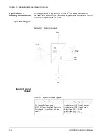
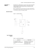
Operation Diagram
Figure 5-3 Operation Diagram
Input and Output
Signals
Table 5-3 Input and Output Signals
Input Signals
Output Signals
Two Analog Reference inputs.
Six Digital Inputs: Start Hand, Start Auto,
Preset Speed (2), Auto Select, and Run
Enable.
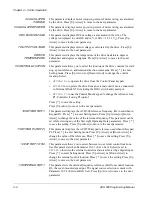
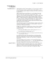
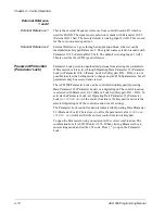
Analog Output AO1: Output Frequency
Analog Output AO2: Output Current
Relay Output RO1: READY
Relay Output RO2: RUN
Relay Output RO3: FAULT
f
A
M
3
Φ
Output
Current
Relay
Outputs
Motor
Ext. Controls
Input
Power
location


