1-96
ACH550-UH User’s Manual
Parameters
Analog Input Reference Correction
Parameter values 9, 10 and 14…17 use the formula in the following table.
Where:
• C = Main reference value
( =
COMM
for values 9, 10 and
=
AI
1 for values 14…17).
• B = Correcting reference
( =
AI
1 for values 9, 10 and
=
AI
2 for values 14…17).
Example:
The figure shows the reference source curves for value
settings 9, 10 and 14…17, where:
• C = 25%.
• P 4012
SETPOINT
MIN
= 0.
• P 4013
SETPOINT
MAX
= 0.
• B varies along the horizontal axis.
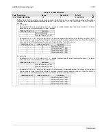
1104
REF1 MIN
0.0…500.0 Hz /
0.1 Hz /
0.0 Hz /
0…30000 rpm
1 rpm
0 rpm
Sets the minimum for external reference 1.
• The minimum analog input signal (as a percent of the full signal in volts or amperes) corresponds to
REF
1
MIN
in
Hz/rpm.
• Parameter 1301
MINIMUM
AI
1 or 1304
MINIMUM
AI
2 sets the minimum analog input signal.
• These parameters (reference and analog min. and max. settings) provide scale and offset adjustment for the
reference.
1105
REF1 MAX
0.0…500.0 Hz /
0.1 Hz /
60.0 Hz (US) /
0…30000 rpm
1 rpm
1800 rpm (US)
Sets the maximum for external reference 1.
• The maximum analog input signal (as a percent of full the signal in volts or amperes) corresponds to
REF
1
MAX
in
Hz/rpm.
• Parameter 1302
MAXIMUM
AI
1 or 1305
MAXIMUM
AI
2 sets the maximum analog input signal.
Group 11: Reference Select
Code Description Range
Resolution
Default
S
Value setting
Calculation of the AI reference
C + B
C value + (B value - 50% of reference value)
C * B
C value · (B value / 50% of reference value)
C - B
(C value + 50% of reference value) - B value
C / B
(C value · 50% of reference value) / B value
120
100
80
60
40
20
0
0
100%
9, 14 (+)
16 (-)
10, 15 (*)
17 (/)
B
Ext ref
Analog
P 1105
P 1104
P 1301
P 1302
input signal
P 1301
P 1302
input signal
Analog
Ext ref
or 1304
or 1305
or 1304
or 1305
(
MAX
)
(
MIN
)
P 1105
P 1104
(
MAX
)
(
MIN
)
Summary of Contents for ACH550-BCR
Page 4: ...iv Manual contents ...
Page 6: ......
Page 12: ...1 8 ACH550 UH User s Manual Table of contents ...
Page 36: ...1 32 ACH550 UH User s Manual Installation ...
Page 70: ...1 66 ACH550 UH User s Manual Application macros ...
Page 335: ...ACH550 UH User s Manual 1 331 Technical data ...
Page 348: ......
Page 382: ...2 36 ACH550 E Clipse Bypass User s Manual Start up ...
Page 398: ...2 52 ACH550 E Clipse Bypass User s Manual Bypass functions overview ...
Page 406: ...2 60 ACH550 E Clipse Bypass User s Manual Application macros ...
Page 544: ...2 198 ACH550 E Clipse Bypass User s Manual Embedded fieldbus ...
Page 584: ...2 238 ACH550 E Clipse Bypass User s Manual Diagnostics ...
Page 608: ......
Page 612: ...3 6 ACH550 UH User s Manual Table of contents ...
Page 622: ...3 16 ACH550 PCR PDR User s Manual Installation ...
Page 641: ......


