ACH550-UH User’s Manual
1-103
Parameters
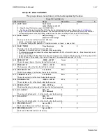
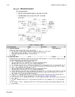
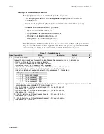
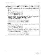
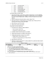
Group 14: RELAY OUTPUTS
This group defines the condition that activates each of the relay outputs. Relay
outputs 4…6 are only available if OREL-01 Relay Output Extension Module is
installed.
Group 14: Relay Outputs
Code Description Range
Resolution
Default
S
1401
RELAY OUTPUT 1
0…47
1
1 (
READY
)
Defines the event or condition that activates relay 1 – what relay output 1 means.
0 =
NOT
SEL
– Relay is not used and is de-energized.
1 =
READY
– Energize relay when drive is ready to function. Requires:
• Run enable signal present.
• No faults exist.
• Supply voltage is within range.
• Emergency Stop command is not on.
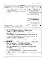
2 =
RUN
– Energize relay when the drive is running.
3 =
FAULT
(-1) – Energize relay when power is applied. De-energizes when a fault occurs.
4 =
FAULT
– Energize relay when a fault is active.
5 =
ALARM
– Energize relay when an alarm is active.
6 =
REVERSED
– Energize relay when motor rotates in reverse direction.
7 =
STARTED
– Energize relay when drive receives a start command (even if Run Enable signal is not present). De-
energized relay when drive receives a stop command or a fault occurs.
8=
SUPRV
1
OVER
– Energize relay when first supervised parameter (3201) exceeds the limit (3203).
starting on page
9 =
SUPRV
1
UNDER
– Energize relay when first supervised parameter (3201) drops below the limit (3202).
starting on page
10 =
SUPRV
2
OVER
– Energize relay when second supervised parameter (3204) exceeds the limit (3206).
starting on page
11 =
SUPRV
2
UNDER
– Energize relay when second supervised parameter (3204) drops below the limit (3205).
starting on page
12 =
SUPRV
3
OVER
– Energize relay when third supervised parameter (3207) exceeds the limit (3209).
starting on page
13 =
SUPRV
3
UNDER
– Energize relay when third supervised parameter (3207) drops below the limit (3208).
starting on page
14 =
AT
SET
POINT
– Energize relay when the output frequency is equal to the reference frequency.
15 =
FAULT
(
RST
) – Energize relay when the drive is in a fault condition and will reset after the programmed auto-reset
delay.
• See parameter 3103
DELAY
TIME
.
16 =
FLT
/
ALARM
– Energize relay when fault or alarm occurs.
17 =
EXT
CTRL
– Energize relay when external control is selected.
18 =
REF
2
SEL
– Energize relay when
EXT
2 is selected.
19 =
CONST
FREQ
– Energize relay when a constant speed is selected.
20 =
REF
LOSS
– Energize relay when reference or active control place is lost.
21 =
OVERCURRENT
– Energize relay when an overcurrent alarm or fault occurs.
22 =
OVERVOLTAGE
– Energize relay when an overvoltage alarm or fault occurs.
23 =
DRIVE
TEMP
– Energize relay when a drive or control board overtemperature alarm or fault occurs.
24 =
UNDERVOLTAGE
– Energize relay when an undervoltage alarm or fault occurs.
25 =
AI
1
LOSS
– Energize relay when
AI
1 signal is lost.
26 =
AI
2
LOSS
– Energize relay when
AI
2 signal is lost.
27 =
MOTOR
TEMP
– Energize relay when a motor overtemperature alarm or fault occurs.
28 =
STALL
– Energize relay when a stall alarm or fault exists.
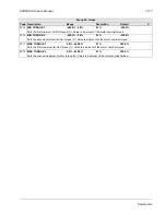
30 =
PID
SLEEP
– Energize relay when the PID sleep function is active.
31 =
PFA
– Use relay to start/stop motor in PFA control (See
• Use this option only when PFA control is used.
• Selection activated / deactivated when drive is not running.
32 =
AUTOCHANGE
– Energize relay when PFA autochange operation is performed.
• Use this option only when PFA control is used.
33 =
FLUX
READY
– Energize relay when the motor is magnetized and able to supply nominal torque (motor has
reached nominal magnetizing).
34 =
USER
MACRO
2 – Energize relay when User Parameter Set 2 is active.
Summary of Contents for ACH550-BCR
Page 4: ...iv Manual contents ...
Page 6: ......
Page 12: ...1 8 ACH550 UH User s Manual Table of contents ...
Page 36: ...1 32 ACH550 UH User s Manual Installation ...
Page 70: ...1 66 ACH550 UH User s Manual Application macros ...
Page 335: ...ACH550 UH User s Manual 1 331 Technical data ...
Page 348: ......
Page 382: ...2 36 ACH550 E Clipse Bypass User s Manual Start up ...
Page 398: ...2 52 ACH550 E Clipse Bypass User s Manual Bypass functions overview ...
Page 406: ...2 60 ACH550 E Clipse Bypass User s Manual Application macros ...
Page 544: ...2 198 ACH550 E Clipse Bypass User s Manual Embedded fieldbus ...
Page 584: ...2 238 ACH550 E Clipse Bypass User s Manual Diagnostics ...
Page 608: ......
Page 612: ...3 6 ACH550 UH User s Manual Table of contents ...
Page 622: ...3 16 ACH550 PCR PDR User s Manual Installation ...
Page 641: ......


