1-130
ACH550-UH User’s Manual
Parameters
3010
STALL FUNCTION
0…2
1
0 (
NOT
SEL
)
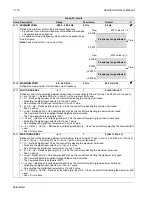
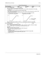
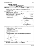
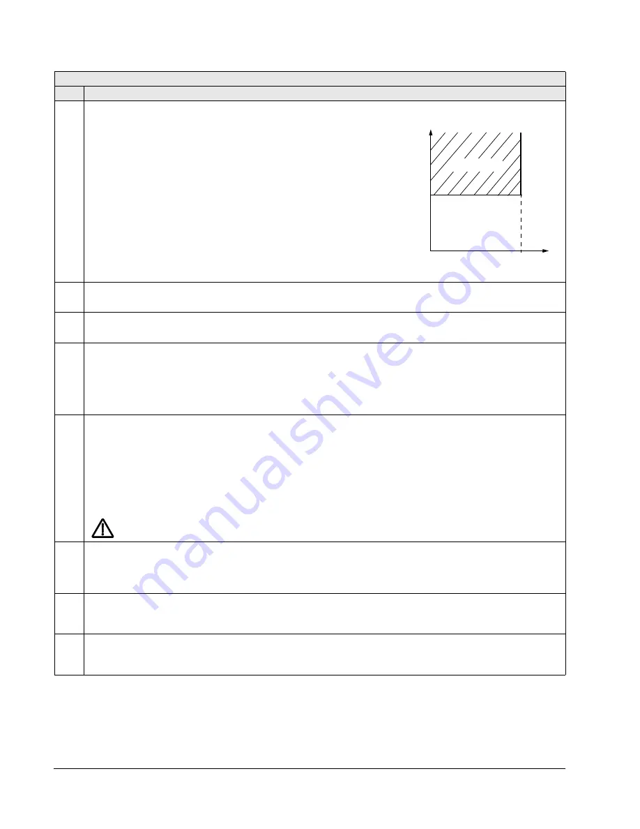
This parameter defines the operation of the Stall function. This
protection is active if the drive operates in the stall region (see the
figure) for the time defined by 3012
STALL
TIME
. The “User Limit” is
by 2017
MAX
TORQUE
1, 2018
MAX
TORQUE
2, or the limit on the
COMM
input.
0 =
NOT
SEL
– Stall protection is not used.
1 =
FAULT
– When the drive operates in the stall region for the time set
by 3012
STALL
TIME
:
• The drive coasts to stop.
• A fault indication is displayed.
2 =
ALARM
– When the drive operates in the stall region for the time set
by 3012
STALL
TIME
:
• An alarm indication is displayed.
• The alarm disappears when the drive is out of the stall region for
half the time set by parameter 3012
STALL
TIME
.
3011
STALL FREQUENCY
0.5…50.0 Hz
0.1 Hz
20.0 Hz
This parameter sets the frequency value for the Stall function. See parameter 3010.
3012
STALL TIME
10…400 s
1 s
20 s
This parameter sets the time value for the Stall function.
3017
EARTH FAULT
0, 1
1
1 (
ENABLE
)
Defines the drive response if the drive detects a ground fault in the motor or motor cables. The drive monitors for
ground faults while the drive is running, and voltage is present on the output. Also see parameter 3023
WIRING
FAULT
.
0 =
DISABLE
– No drive response to ground faults.
Note:
Disabling earth fault (ground fault) may void the warranty.
1 =
ENABLE
– Ground faults display fault 16 (
EARTH
FAULT
), and (if running) the drive coasts to stop.
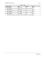
3018
COMM FAULT FUNC
0…3
1
0 (
NOT
SEL
)
Defines the drive response if the fieldbus communication is lost.
0 =
NOT
SEL
– No response.
1 =
FAULT
– Displays a fault (28,
SERIAL
1
ERR
) and the drive coasts to stop.
2 =
CONST
SP
7 – Displays an alarm (2005,
I
/
O
COMM
) and sets speed using 1208
CONST
SPEED
7. This “alarm speed”
remains active until the fieldbus writes a new reference value.
3 =
LAST
SPEED
– Displays an alarm (2005,
I
/
O
COMM
) and sets speed using the last operating level. This value is the
average speed over the last 10 seconds. This “alarm speed” remains active until the fieldbus writes a new
reference value.
WARNING!
If you select
CONST
SP
7, or
LAST
SPEED
, make sure that continued operation is safe when
fieldbus communication is lost.
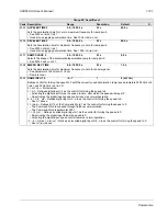
3019
COMM FAULT TIME
0.0…600.0 s
0.1 s
10.0 s
Sets the communication fault time used with 3018
COMM
FAULT
FUNC
.
• Brief interruptions in the fieldbus communication are not treated as faults if they are less than the
COMM
FAULT
TIME
value.
3021
AI1 FAULT LIMIT
0.0…100.0%
0.1%
0.0%
Sets a fault level for analog input 1.
• See 3001
AI
<
MIN
FUNCTION
.
3022
AI2 FAULT LIMIT
0.0…100.0%
0.1%
0.0%
Sets a fault level for analog input 2.
• See 3001
AI
<
MIN
FUNCTION
.
Group 30: Fault Functions
Code Description Range
Resolution
Default
S
95%
limit
User
Stall region
Torque/
Current
f
Stall frequency
P 3011
Summary of Contents for ACH550-BCR
Page 4: ...iv Manual contents ...
Page 6: ......
Page 12: ...1 8 ACH550 UH User s Manual Table of contents ...
Page 36: ...1 32 ACH550 UH User s Manual Installation ...
Page 70: ...1 66 ACH550 UH User s Manual Application macros ...
Page 335: ...ACH550 UH User s Manual 1 331 Technical data ...
Page 348: ......
Page 382: ...2 36 ACH550 E Clipse Bypass User s Manual Start up ...
Page 398: ...2 52 ACH550 E Clipse Bypass User s Manual Bypass functions overview ...
Page 406: ...2 60 ACH550 E Clipse Bypass User s Manual Application macros ...
Page 544: ...2 198 ACH550 E Clipse Bypass User s Manual Embedded fieldbus ...
Page 584: ...2 238 ACH550 E Clipse Bypass User s Manual Diagnostics ...
Page 608: ......
Page 612: ...3 6 ACH550 UH User s Manual Table of contents ...
Page 622: ...3 16 ACH550 PCR PDR User s Manual Installation ...
Page 641: ......

