1-292
ACH550-UH User’s Manual
Maintenance
• Remove the front cover.
• Lift the fan out and disconnect the cable.
• Install the fan in reverse order.
• Restore power.
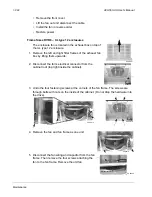
Frame Sizes R7/R8 – UL type 12 enclosures
The enclosure fan is located in the exhaust box on top of
the UL type 12 enclosure.
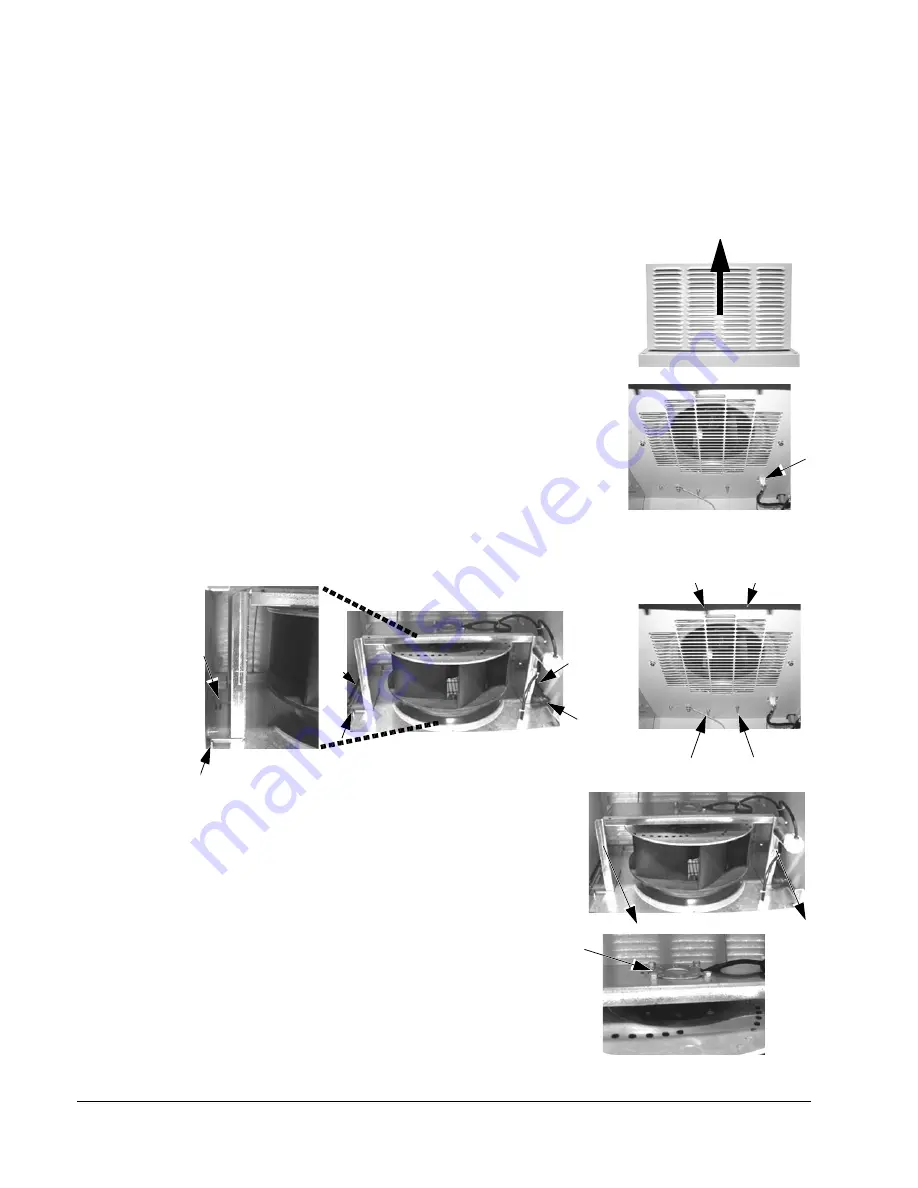
1. Remove the left and right filter frames of the exhaust fan
box by lifting them upwards.
2. Disconnect the fan’s electrical connector from the
cabinet roof (top right inside the cabinet).
3. Undo the four fastening screws at the corners of the fan frame. The screws are
through bolts with nuts on the inside of the cabinet. (Do not drop the hardware into
the drive).
4. Remove the fan and fan frame as one unit.
5. Disconnect the fan wiring and capacitor from the fan
frame. Then remove the four screws attaching the
fan to the fan frame. Remove the old fan.
PC00021
PC00018
PC00017
PC00014
PC00018
PC00014
PC00020
Summary of Contents for ACH550-BCR
Page 4: ...iv Manual contents ...
Page 6: ......
Page 12: ...1 8 ACH550 UH User s Manual Table of contents ...
Page 36: ...1 32 ACH550 UH User s Manual Installation ...
Page 70: ...1 66 ACH550 UH User s Manual Application macros ...
Page 335: ...ACH550 UH User s Manual 1 331 Technical data ...
Page 348: ......
Page 382: ...2 36 ACH550 E Clipse Bypass User s Manual Start up ...
Page 398: ...2 52 ACH550 E Clipse Bypass User s Manual Bypass functions overview ...
Page 406: ...2 60 ACH550 E Clipse Bypass User s Manual Application macros ...
Page 544: ...2 198 ACH550 E Clipse Bypass User s Manual Embedded fieldbus ...
Page 584: ...2 238 ACH550 E Clipse Bypass User s Manual Diagnostics ...
Page 608: ......
Page 612: ...3 6 ACH550 UH User s Manual Table of contents ...
Page 622: ...3 16 ACH550 PCR PDR User s Manual Installation ...
Page 641: ......

