ACH550-UH User’s Manual
1-305
Technical data
Ground connections
For personnel safety, proper operation and to reduce electromagnetic emission/pick-
up, the drive and the motor must be grounded at the installation site.
• Conductors must be adequately sized as required by safety regulations.
• Power cable shields must be connected to the drive PE terminal in order to meet
safety regulations.
• Power cable shields are suitable for use as equipment grounding conductors only
when the shield conductors are adequately sized as required by safety
regulations.
• In multiple drive installations, do not connect drive terminals in series.
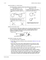
Unsymmetrically grounded networks
WARNING!
Do not attempt to install or remove EM1 or EM3 screws while power is
applied to the drive’s input terminals.
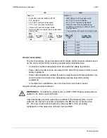
Unsymmetrically grounded networks are defined in the following table. In such
networks, the internal connection provided by the EM3 screw (on frame sizes
R1…R4 only) must be disconnected by removing EM3. If the grounding
configuration of the network is unknown, remove EM3.
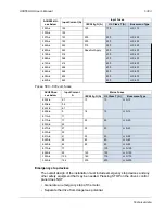
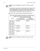
465
2x4/0
474
2x250
534
2x300
615
2x350
711
2x500
IEC
NEC
Based on:
• EN 60204-1 and IEC 60364-5-2/2001
• PVC insulation
• 30 °C (86 °F) ambient temperature
• 70 °C (158 °F) surface temperature
• Cables with concentric copper shield
• Not more than nine cables laid on cable ladder
side by side.
Based on:
• NEC Table 310-16 for copper wires
• 90 °C (194 °F) wire insulation
• 40 °C (104 °F) ambient temperature
• Not more than three current-carrying
conductors in raceway or cable, or earth
(directly buried).
• Copper cables with concentric copper shield
Max
Load
Current
(A)
Cu Cable
(mm
2
)
Max
Load
Current
(A)
Al Cable
(mm
2
)
Max Load
Current
(A)
Cu Wire Size
(AWG/kcmil)
Summary of Contents for ACH550-BCR
Page 4: ...iv Manual contents ...
Page 6: ......
Page 12: ...1 8 ACH550 UH User s Manual Table of contents ...
Page 36: ...1 32 ACH550 UH User s Manual Installation ...
Page 70: ...1 66 ACH550 UH User s Manual Application macros ...
Page 335: ...ACH550 UH User s Manual 1 331 Technical data ...
Page 348: ......
Page 382: ...2 36 ACH550 E Clipse Bypass User s Manual Start up ...
Page 398: ...2 52 ACH550 E Clipse Bypass User s Manual Bypass functions overview ...
Page 406: ...2 60 ACH550 E Clipse Bypass User s Manual Application macros ...
Page 544: ...2 198 ACH550 E Clipse Bypass User s Manual Embedded fieldbus ...
Page 584: ...2 238 ACH550 E Clipse Bypass User s Manual Diagnostics ...
Page 608: ......
Page 612: ...3 6 ACH550 UH User s Manual Table of contents ...
Page 622: ...3 16 ACH550 PCR PDR User s Manual Installation ...
Page 641: ......


