ACH550-UH User’s Manual
1-311
Technical data
Motor cable shielding
Motor cables require shielding using conduit, armored cable or shielded cable.
• Conduit – When using conduit:
– Bridge joints with a ground conductor bonded to the conduit on each side of
the joint.
– Bond conduit run to the drive enclosure.
– Use a separate conduit run for motor cables (also separate input power and
control cables).
– Use a separate conduit run for each drive.
• Armored Cable – When using armored cable:
– Use six-conductor (3 phases and 3 grounds), type MC continuous corrugated
aluminum armor cable with symmetrical grounds.
– Armored motor cable can share a cable tray with input power cables, but not
with control cables.
• Shielded Cable – For shielded cable details, see
Motor cable requirements for CE
below.
Grounding
See
above.
For CE compliant installations and installations where EMC emissions must be
minimized, see
on page
.
Drive’s motor connection terminals
The drive’s motor and input power terminals have the same specifications. See
Drive’s power connection terminals
above.
Motor cable requirements for CE & C-Tick compliance
The requirements in this section apply for CE or C-Tick compliance.
Minimum requirement (CE & C-Tick)
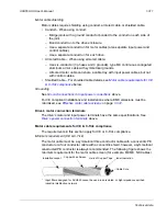
The motor cable must be a symmetrical three conductor cable with a concentric PE
conductor or a four conductor cable with a concentric shield, however, a symmetrical
constructed PE conductor is always recommended. The following figure shows the
minimum requirement for the motor cable screen (for example, MCMK, NK Cables).
* Input filters designed for ACH550 cannot be used in an isolated, or high impedance earthed
industrial distribution network.
Insulation Jacket
Copper Wire Screen
Helix of Copper Tape
Cable Core
Inner Insulation
Summary of Contents for ACH550-BCR
Page 4: ...iv Manual contents ...
Page 6: ......
Page 12: ...1 8 ACH550 UH User s Manual Table of contents ...
Page 36: ...1 32 ACH550 UH User s Manual Installation ...
Page 70: ...1 66 ACH550 UH User s Manual Application macros ...
Page 335: ...ACH550 UH User s Manual 1 331 Technical data ...
Page 348: ......
Page 382: ...2 36 ACH550 E Clipse Bypass User s Manual Start up ...
Page 398: ...2 52 ACH550 E Clipse Bypass User s Manual Bypass functions overview ...
Page 406: ...2 60 ACH550 E Clipse Bypass User s Manual Application macros ...
Page 544: ...2 198 ACH550 E Clipse Bypass User s Manual Embedded fieldbus ...
Page 584: ...2 238 ACH550 E Clipse Bypass User s Manual Diagnostics ...
Page 608: ......
Page 612: ...3 6 ACH550 UH User s Manual Table of contents ...
Page 622: ...3 16 ACH550 PCR PDR User s Manual Installation ...
Page 641: ......

