2-38
ACH550 E-Clipse Bypass User’s Manual
Bypass functions overview
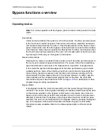
Smoke Control Mode (Override 1)
In the Smoke Control (Override 1) mode, the motor is powered by AC line power
through the bypass contactor. The source of the start command is internal and
unaffected by external stop commands. The system also ignores all commands from
either the drive or bypass control panels when in this mode. The user can switch to
the Smoke Control mode by closing the Smoke Control input contact (DI6). When
the Smoke Control input contact is closed, the system is forced to bypass and runs
the motor. The Motor Run LED flashes green when the system is in override. While
in Smoke Control mode, the system does not respond to some inputs and does
respond to other inputs. The system will ignore low priority safeties such as
FreezeStats and return duct smoke detectors. While in Smoke Control mode, the
system will respond to high priority safeties such as high static pressure and damper
end-switch proofs. The system will always respond to the electronic motor overload
protection included in the bypass controller. See the diagrams on page
for
suggested wiring of typical customer inputs. One diagram is to be used for supply
side fans and the other diagram is used for return / exhaust side fans.
Normally when the Smoke Control input contact is switched from closed to open, the
system returns to the operating mode that existed prior to entering Override and can
again be controlled using the Drive and Bypass keys. The exception to this is when
the Advanced Override (Override 2) input contact is closed, in which case the
system switches to Advanced Override mode.
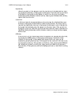
Supervisory Mode
In the Bypass Supervisory mode, the bypass has the ability to control a process by
cycling the bypass contactor on and off with a hysteresis control. In this mode the
motor is powered by AC line power through the bypass contactor. The source of the
bypass start/stop commands is determined by the Auto or Hand mode selection of
the bypass’ control panel. Commands come from the analog input level (AI2) on the
ACH550 drive when the Auto mode has been selected or directly from the bypass
control panel when the Hand mode has been selected (manual). Bypass
supervisory control is enabled and configured in parameter Group 32. Once
enabled, the user can normally switch to the Supervisory Bypass mode by pressing
the Bypass key on the bypass control panel. Alternative methods of bypass control
called Overrides are also available. Refer to the following descriptions of the
Override modes. The Supervisory control only operates in Bypass / Auto mode. If
the user presses the Hand or Off buttons, operation is the same as normal bypass
operation. If the user selects Drive mode, the Supervisory operation is also stopped.
Returning to Bypass / Auto mode will put the bypass back to Supervisory mode.
Bypass
Supervisory
Controller
Parameter
0121
ACH550
AI2
Temp
Sensor
Bypass
Contactor
Output =
1 if AI2 > Start Level
0 if AI2 < Stop level
unchanged otherwise
= AI2
Output =
1 if AI2 < Start Level
0 if AI2 > Stop level
unchanged otherwise
Start >=
Stop
Start <
Stop
Bypass mode
AND AUTO
AND NOT OVERRIDE
AND 32.01 = 1
Drive mode
OR NOT AUTO
OR OVERRIDE
OR 32.01 = 0
Traditional
Contactor
Control
Transitions subject
to Start Delay and
Stop Delay
Summary of Contents for ACH550-BCR
Page 4: ...iv Manual contents ...
Page 6: ......
Page 12: ...1 8 ACH550 UH User s Manual Table of contents ...
Page 36: ...1 32 ACH550 UH User s Manual Installation ...
Page 70: ...1 66 ACH550 UH User s Manual Application macros ...
Page 335: ...ACH550 UH User s Manual 1 331 Technical data ...
Page 348: ......
Page 382: ...2 36 ACH550 E Clipse Bypass User s Manual Start up ...
Page 398: ...2 52 ACH550 E Clipse Bypass User s Manual Bypass functions overview ...
Page 406: ...2 60 ACH550 E Clipse Bypass User s Manual Application macros ...
Page 544: ...2 198 ACH550 E Clipse Bypass User s Manual Embedded fieldbus ...
Page 584: ...2 238 ACH550 E Clipse Bypass User s Manual Diagnostics ...
Page 608: ......
Page 612: ...3 6 ACH550 UH User s Manual Table of contents ...
Page 622: ...3 16 ACH550 PCR PDR User s Manual Installation ...
Page 641: ......


