ACH550-PCR/PDR User’s Manual
3-9
Installation
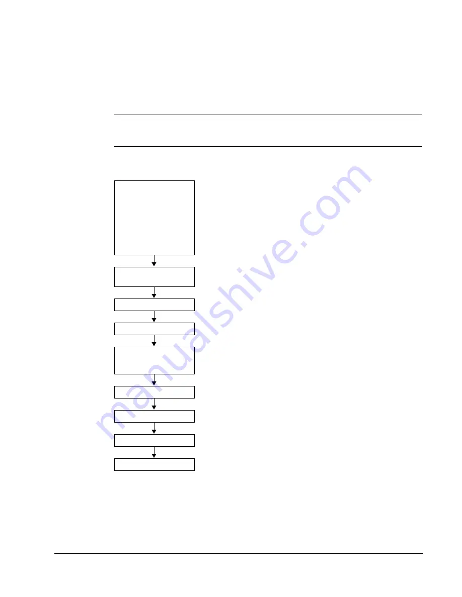
Installation flow chart
The installation of Input Disconnect configurations for ACH550 drives follows the
outline below. The steps must be carried out in the order shown. At the right of each
step are references to the detailed information needed for the correct installation of
the unit.
Note:
References in the middle column below are to the ACH550-UH User’s
Manual. References in the third column below are to this manual.
Task
Refer to the ACH550-UH
User’s Manual
section
Additional Reference in this
Manual
PREPARE
for
installation
•
on page
•
Also see
PREPARE
the mounting
location
--
REMOVE
the front cover
--
MOUNT
the drive
--
INSTALL
wiring
and
Installing the wiring (supplement to
ACH550-UH User’s Manual)
on
.
CHECK
installation
--
RE-INSTALL
the cover
--
APPLY
power
--
START-UP
--
Summary of Contents for ACH550-BCR
Page 4: ...iv Manual contents ...
Page 6: ......
Page 12: ...1 8 ACH550 UH User s Manual Table of contents ...
Page 36: ...1 32 ACH550 UH User s Manual Installation ...
Page 70: ...1 66 ACH550 UH User s Manual Application macros ...
Page 335: ...ACH550 UH User s Manual 1 331 Technical data ...
Page 348: ......
Page 382: ...2 36 ACH550 E Clipse Bypass User s Manual Start up ...
Page 398: ...2 52 ACH550 E Clipse Bypass User s Manual Bypass functions overview ...
Page 406: ...2 60 ACH550 E Clipse Bypass User s Manual Application macros ...
Page 544: ...2 198 ACH550 E Clipse Bypass User s Manual Embedded fieldbus ...
Page 584: ...2 238 ACH550 E Clipse Bypass User s Manual Diagnostics ...
Page 608: ......
Page 612: ...3 6 ACH550 UH User s Manual Table of contents ...
Page 622: ...3 16 ACH550 PCR PDR User s Manual Installation ...
Page 641: ......


