3-14
ACH550-PCR/PDR User’s Manual
Installation
Install the line input wiring
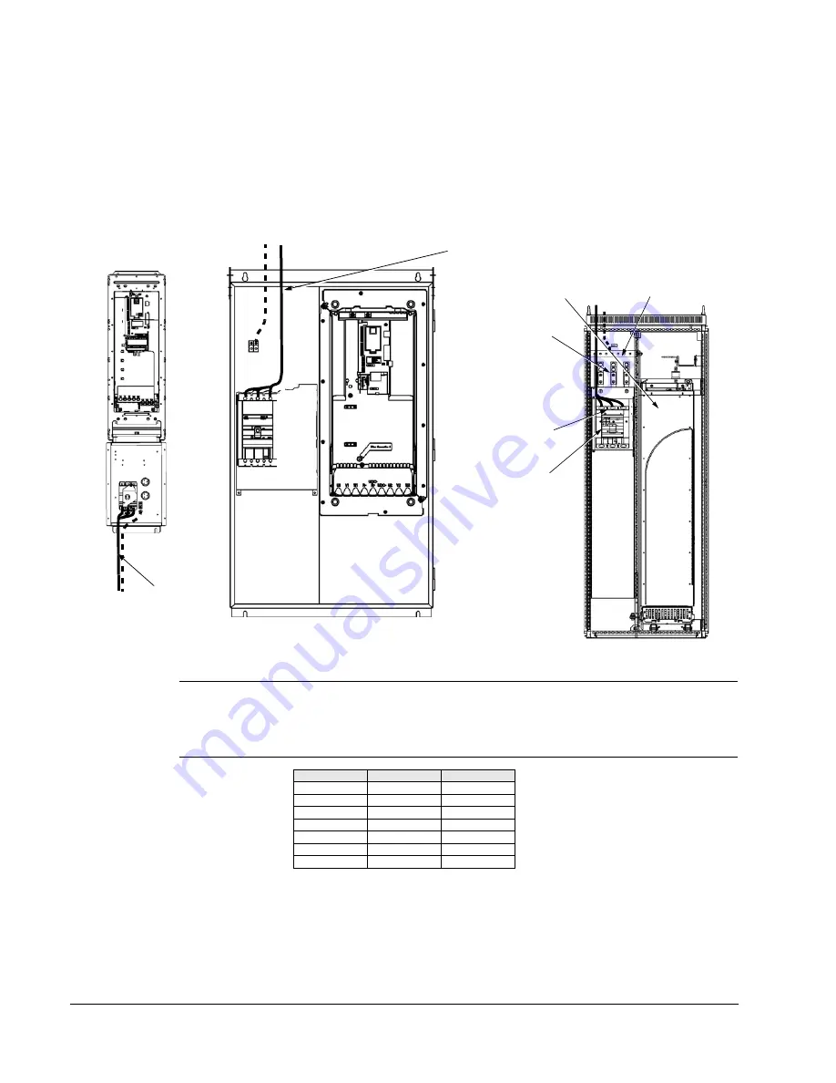
Line input connections – standard drive with input disconnect configurations
Connect input power to the terminals of the disconnect switch or circuit breaker.
Connect the equipment grounding conductor to the ground lug at the top of the
enclosure. The figure below shows the connection points for Standard Drive with
Input Disconnect configurations.
Note:
The terminals on disconnect switches for the following rated ACH550-PDR
products is 7 in-lbs. Do not use a power driver or over tighten to prevent breaking
screw heads or stripping the terminal.
230 VAC
460 VAC
600 VAC
-04A6-2
-03A3-4
-02A7-6
-06A6-2
-04A1-4
-03A9-6
-07A5-2
-06A9-4
-06A1-6
-012A-2
-08A8-4
-09A0-6
-017A-2
-012A-4
-011A-6
-024A-2
-015A-4
-017A-6
-031A-2
-023A-4
Input
Power
Input
Power
UL Type / NEMA 1 & 12
UL Type / NEMA 1 & 12
Enclosures
Enclosures
UL Type / NEMA 1 & 12
Enclosures
Dashed line is ground run.
Vertical Construction
Hinged Door Wall Mount
Floor Mount
ACH550
Input Power
Terminals
Motor
Terminals
Ground Lug
Bar
Disconnect Switch
or Circuit Breaker
Summary of Contents for ACH550-BCR
Page 4: ...iv Manual contents ...
Page 6: ......
Page 12: ...1 8 ACH550 UH User s Manual Table of contents ...
Page 36: ...1 32 ACH550 UH User s Manual Installation ...
Page 70: ...1 66 ACH550 UH User s Manual Application macros ...
Page 335: ...ACH550 UH User s Manual 1 331 Technical data ...
Page 348: ......
Page 382: ...2 36 ACH550 E Clipse Bypass User s Manual Start up ...
Page 398: ...2 52 ACH550 E Clipse Bypass User s Manual Bypass functions overview ...
Page 406: ...2 60 ACH550 E Clipse Bypass User s Manual Application macros ...
Page 544: ...2 198 ACH550 E Clipse Bypass User s Manual Embedded fieldbus ...
Page 584: ...2 238 ACH550 E Clipse Bypass User s Manual Diagnostics ...
Page 608: ......
Page 612: ...3 6 ACH550 UH User s Manual Table of contents ...
Page 622: ...3 16 ACH550 PCR PDR User s Manual Installation ...
Page 641: ......


