ACH550-UH User’s Manual
1-119
Parameters
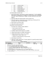
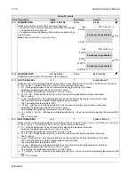
2104
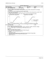
DC HOLD CTL
0…2
1
0 (
NOT
SEL
)
Selects whether DC current is used for braking or DC Hold.
0 =
NOT
SEL
– Disables the DC current operation.
1 =
DC
HOLD
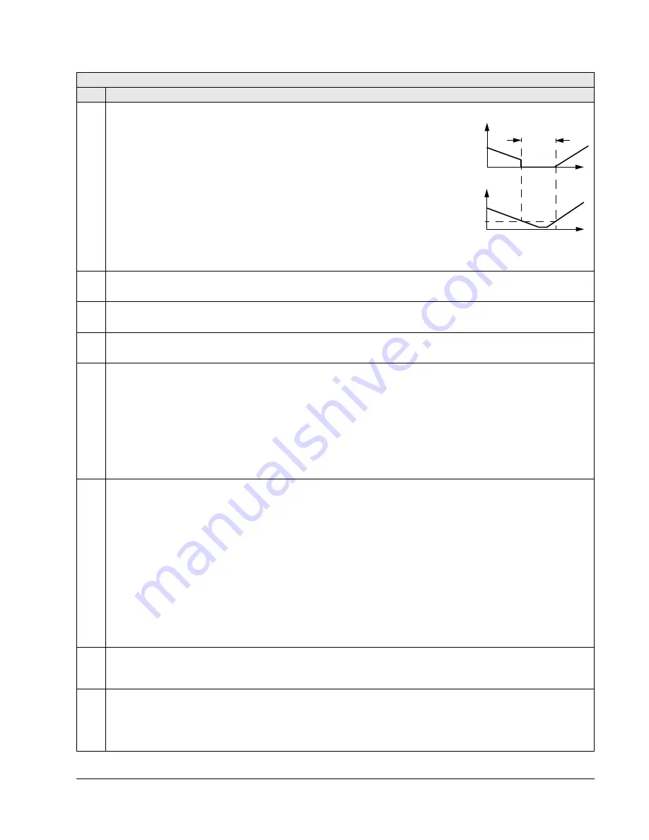
– Enables the DC Hold function. See the diagram.
• Requires parameter 9904
MOTOR
CTRL
MODE
= 1 (
VECTOR
:
SPEED
)
• Stops generating sinusoidal current and injects DC into the motor when
both the reference and the motor speed drop below the value of
parameter 2105.
• When the reference rises above the level of parameter 2105 the drive
resumes normal operation.
2 =
DC
BRAKING
– Enables the DC Injection Braking after modulation has
stopped.
• If parameter 2102
STOP
FUNCTION
is 1 (
COAST
), braking is applied after
start is removed.
• If parameter 2102
STOP
FUNCTION
is 2 (
RAMP
), braking is applied after ramp.
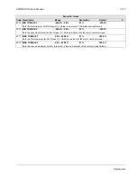
2105
DC HOLD SPEED
0…360 rpm
1 rpm
5 rpm
Sets the speed for DC Hold. Requires that parameter 2104
DC
HOLD
CTL
= 1 (
DC
HOLD
).
2106
DC CURR REF
0…100%
1%
30%
Defines the DC current control reference as a percentage of parameter 9906
MOTOR
NOM
CURR
.
2107
DC BRAKE TIME
0.0…250.0 s
0.1 s
0.0 s
Defines the DC brake time after modulation has stopped, if parameter 2104 is 2 (
DC
BRAKING
).
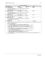
2108
START INHIBIT
0, 1
1
0 (
OFF
)
Sets the Start inhibit function on or off. If the drive is not actively started and running, the Start inhibit function ignores
a pending start command in any of the following situations and a new start command is required:
• A fault is reset.
• Run Enable (parameter 1601) activates while start command is active.
• Mode changes from local to remote.
• Control switches from
EXT
1 to
EXT
2.
• Control switches from
EXT
2 to
EXT
1.
0 =
OFF
– Disables the Start inhibit function.
1 =
ON
– Enables the Start inhibit function.
2109
EMERG STOP SEL
-6…6
1
0 (
NOT
SEL
)
Defines control of the Emergency stop command. When activated:
• Emergency stop decelerates the motor using the emergency stop ramp (parameter 2208
EMERG
DEC
TIME
).
• Requires an external stop command and removal of the emergency stop command before drive can restart.
0 =
NOT
SEL
– Disables the Emergency stop function through digital inputs.
1 =
DI
1 – Defines digital input
DI
1 as the control for Emergency stop command.
• Activating the digital input issues an Emergency stop command.
• De-activating the digital input removes the Emergency stop command.
2…6 =
DI
2…
DI
6 – Defines digital input
DI
2…
DI
6 as the control for Emergency stop command.
• See
DI
1 above.
-1 =
DI
1(
INV
) – Defines an inverted digital input
DI
1 as the control for Emergency stop command.
• De-activating the digital input issues an Emergency stop command.
• Activating the digital input removes the Emergency stop command.
-2…-6 =
DI
2(
INV
)…
DI
6(
INV
) – Defines an inverted digital input
DI
2…
DI
6 as the control for Emergency stop command.
• See
DI
1(
INV
) above.
2110
TORQ BOOST CURR
15…300%
1%
100%
Sets the maximum supplied current during torque boost.
• See parameter 2101
START
FUNCTION
.
2113
START DELAY
0.0…60.00 s
0.01 s
0.00 s
Defines the Start delay. After the conditions for start have been fulfilled, the drive waits until the delay has elapsed
and then starts the motor. Start delay can be used with all start modes.
• If
START
DELAY
= zero, the delay is disabled.
• During the Start delay, alarm 2028
START
DELAY
is shown.
Group 21: Start/Stop
Code Description Range
Resolution
Default
S
speed
Ref
DC hold
DC hold
Motor
speed
T
T
Summary of Contents for ACH550-BCR
Page 4: ...iv Manual contents ...
Page 6: ......
Page 12: ...1 8 ACH550 UH User s Manual Table of contents ...
Page 36: ...1 32 ACH550 UH User s Manual Installation ...
Page 70: ...1 66 ACH550 UH User s Manual Application macros ...
Page 335: ...ACH550 UH User s Manual 1 331 Technical data ...
Page 348: ......
Page 382: ...2 36 ACH550 E Clipse Bypass User s Manual Start up ...
Page 398: ...2 52 ACH550 E Clipse Bypass User s Manual Bypass functions overview ...
Page 406: ...2 60 ACH550 E Clipse Bypass User s Manual Application macros ...
Page 544: ...2 198 ACH550 E Clipse Bypass User s Manual Embedded fieldbus ...
Page 584: ...2 238 ACH550 E Clipse Bypass User s Manual Diagnostics ...
Page 608: ......
Page 612: ...3 6 ACH550 UH User s Manual Table of contents ...
Page 622: ...3 16 ACH550 PCR PDR User s Manual Installation ...
Page 641: ......


