1-310
ACH550-UH User’s Manual
Technical data
Ground fault protection
ACH550 internal fault logic detects ground faults in the drive, motor, or motor cable.
This fault logic:
• Is NOT a personal safety or fire protection feature.
• Can be set to trigger only a warning using parameter 3017
EARTH
FAULT
.
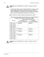
• Could be tripped by leakage currents (input power to ground) associated with the
use of an optional RFI/EMC filter.
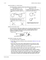
Grounding and routing
Background
Motor cables require extra care in grounding and routing. The reasons have to do
with the following factors:
• Parasitic capacitance – Capacitors are, essentially, conductors that don’t touch,
but are in close proximity to each other. So, for example, there is a weak
capacitive connection between cables and any conductors they are near. Such
unintentional, but inevitable conductive paths are called parasitic capacitors.
Currents flowing through these paths often create problems. For example, current
leaks to control cables can create noise interference, leaks to the motor can
damage bearings, and leaks to the drive or other electronic cabinets can damage
components.
• Proximity – As the conductors get closer together, capacitance increases.
• Proximal area – As the area in close proximity increases, the capacitance
increases, e.g. close parallel paths increase parasitic capacitance between
conductors.
• AC frequency – For a given capacitance, increased AC frequency increases
current conductance. Hence, capacitive paths that are negligible at 50/60 Hz can
be very significant conductors at 8,000 Hz. Motor cable signals are pulses at up to
8,000 Hz and the common mode frequency can reach 48,000 Hz (8k Hz x 3
phases x 2 pulse edges).
• Alternate paths – Where multiple paths exist, the most conductive path draws the
most current. So, the ground wiring must be a significantly better path, in order to
reduce the current in the alternate paths, the paths through parasitic capacitors.
The high frequencies associated with motor cables also increase the potential for
electromagnetic noise radiation. See
Motor cable requirements for CE & C-Tick
on page
.
Summary of Contents for ACH550-BCR
Page 4: ...iv Manual contents ...
Page 6: ......
Page 12: ...1 8 ACH550 UH User s Manual Table of contents ...
Page 36: ...1 32 ACH550 UH User s Manual Installation ...
Page 70: ...1 66 ACH550 UH User s Manual Application macros ...
Page 335: ...ACH550 UH User s Manual 1 331 Technical data ...
Page 348: ......
Page 382: ...2 36 ACH550 E Clipse Bypass User s Manual Start up ...
Page 398: ...2 52 ACH550 E Clipse Bypass User s Manual Bypass functions overview ...
Page 406: ...2 60 ACH550 E Clipse Bypass User s Manual Application macros ...
Page 544: ...2 198 ACH550 E Clipse Bypass User s Manual Embedded fieldbus ...
Page 584: ...2 238 ACH550 E Clipse Bypass User s Manual Diagnostics ...
Page 608: ......
Page 612: ...3 6 ACH550 UH User s Manual Table of contents ...
Page 622: ...3 16 ACH550 PCR PDR User s Manual Installation ...
Page 641: ......

