1-316
ACH550-UH User’s Manual
Technical data
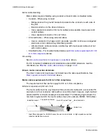
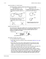
Note:
Triacs used as sources for drive inputs, may have
excessive leakage current in the OFF state, enough to
read as ON to drive inputs. Driving two or more inputs,
divides the leakage current, reducing or eliminating the
problem. An alternative is to add a small capacitive load
– see figure.
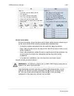
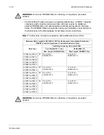
WARNING!
Relay coils generate noise spikes
in response to steps in applied power. To avoid
drive damage from such spikes, all AC relay
coils mounted across drive inputs require R-C
snubbers, and all DC relay coils mounted
across drive outputs require diodes – see
figure.
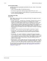
Analog cables
Recommendations for analog signal runs:
• Use double shielded, twisted pair cable.
• Use one individually shielded pair for each signal.
• Do not use a common return for different analog signals.
Digital cables
Recommendation for digital signal runs: A double shielded cable is the best
alternative, but single-shielded, twisted, multi-pair cable is also usable.
Control panel cable
If the control panel is connected to the drive with a cable, use only Category 5 Patch
ethernet cable.
Drive’s control connection terminals
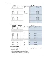
The following table provides specifications for the drive’s control terminals
Control terminal descriptions
The following full-page diagram provides a general description of the control
terminals on the drive. For specific application details, see the
page
Note:
Terminals 3, 6, and 9 are at the same potential.
Frame Size
Control
Maximum Wire Size
Torque
mm
2
AWG
Nm
lb-ft
All
1.5
16
0.4
0.3
1.0 uF
Drive
Inputs
Triac
250 V
33 Ohm
0.47 uF
AC Coil
Drive
Typical R-C
Snubber
DC Coil
Drive
Diode
+
-
Inputs
Outputs
Summary of Contents for ACH550-BCR
Page 4: ...iv Manual contents ...
Page 6: ......
Page 12: ...1 8 ACH550 UH User s Manual Table of contents ...
Page 36: ...1 32 ACH550 UH User s Manual Installation ...
Page 70: ...1 66 ACH550 UH User s Manual Application macros ...
Page 335: ...ACH550 UH User s Manual 1 331 Technical data ...
Page 348: ......
Page 382: ...2 36 ACH550 E Clipse Bypass User s Manual Start up ...
Page 398: ...2 52 ACH550 E Clipse Bypass User s Manual Bypass functions overview ...
Page 406: ...2 60 ACH550 E Clipse Bypass User s Manual Application macros ...
Page 544: ...2 198 ACH550 E Clipse Bypass User s Manual Embedded fieldbus ...
Page 584: ...2 238 ACH550 E Clipse Bypass User s Manual Diagnostics ...
Page 608: ......
Page 612: ...3 6 ACH550 UH User s Manual Table of contents ...
Page 622: ...3 16 ACH550 PCR PDR User s Manual Installation ...
Page 641: ......


