ACH550-UH User’s Manual
1-29
Installation
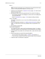
Apply power
Always re-install the covers before turning power on.
WARNING!
The ACH550 will start up automatically at power up, if the external run
command is on.
1. Apply input power.
When power is applied to the ACH550, the green LED comes on.
WARNING!
Even when the motor is stopped, dangerous voltage is present at the
power circuit terminals U1, V1, W1 (L1, L2, L3) and U2, V2, W2 (T1, T2, T3) and,
depending on the frame size, UDC+ and UDC-, or BRK+ and BRK-.
Note:
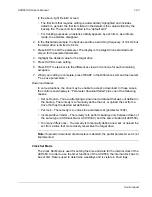
Before increasing motor speed, check that the motor is running in the desired
direction. To change rotation direction, switch motor leads as shown below. Power
circuit terminal designation and location varies depending on the frame size and
some terminals are not used (UDC+ and UDC-, or BRK+ and BRK-). Refer to pages
and
for specific terminal layouts.
U1
V1
W1
U2
V2
W2
L1
L2
L3
Motor
Drive
Input
FM
U1
V1
W1
U2
V2
W2
L1
L2
L3
Motor
Drive
Input
To change rotation direction,
switch motor leads
GND
GND
GND
GND
Summary of Contents for ACH550-BCR
Page 4: ...iv Manual contents ...
Page 6: ......
Page 12: ...1 8 ACH550 UH User s Manual Table of contents ...
Page 36: ...1 32 ACH550 UH User s Manual Installation ...
Page 70: ...1 66 ACH550 UH User s Manual Application macros ...
Page 335: ...ACH550 UH User s Manual 1 331 Technical data ...
Page 348: ......
Page 382: ...2 36 ACH550 E Clipse Bypass User s Manual Start up ...
Page 398: ...2 52 ACH550 E Clipse Bypass User s Manual Bypass functions overview ...
Page 406: ...2 60 ACH550 E Clipse Bypass User s Manual Application macros ...
Page 544: ...2 198 ACH550 E Clipse Bypass User s Manual Embedded fieldbus ...
Page 584: ...2 238 ACH550 E Clipse Bypass User s Manual Diagnostics ...
Page 608: ......
Page 612: ...3 6 ACH550 UH User s Manual Table of contents ...
Page 622: ...3 16 ACH550 PCR PDR User s Manual Installation ...
Page 641: ......


