2-12
ACH550 E-Clipse Bypass User’s Manual
Installation
Wiring overview (supplement to ACH550-UH User’s Manual)
Connection diagrams – Vertical E-Clipse Bypass
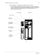
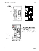
ACH550 Vertical E-Clipse Bypass units are configured for wiring access from the
bottom only. The following figure shows the Vertical E-Clipse Bypass wiring
connection points. Refer to the ACH550-UH User’s Manual on page
for
control connections to the drive.
BP0054
ACH550
E-Clipse Bypass
Control Board
Terminals (X2)
Disconnect Switch
or Circuit Breaker
Output
Input Power
Output Ground
Lug(s)
Cable
Terminals
Output
Ground Lug(s)
Output
Terminals
V1/V2
V3/V4
Service Switch
(Optional)
Input
Ground Lug
Terminals
Service Switch
(Optional)
Summary of Contents for ACH550-BCR
Page 4: ...iv Manual contents ...
Page 6: ......
Page 12: ...1 8 ACH550 UH User s Manual Table of contents ...
Page 36: ...1 32 ACH550 UH User s Manual Installation ...
Page 70: ...1 66 ACH550 UH User s Manual Application macros ...
Page 335: ...ACH550 UH User s Manual 1 331 Technical data ...
Page 348: ......
Page 382: ...2 36 ACH550 E Clipse Bypass User s Manual Start up ...
Page 398: ...2 52 ACH550 E Clipse Bypass User s Manual Bypass functions overview ...
Page 406: ...2 60 ACH550 E Clipse Bypass User s Manual Application macros ...
Page 544: ...2 198 ACH550 E Clipse Bypass User s Manual Embedded fieldbus ...
Page 584: ...2 238 ACH550 E Clipse Bypass User s Manual Diagnostics ...
Page 608: ......
Page 612: ...3 6 ACH550 UH User s Manual Table of contents ...
Page 622: ...3 16 ACH550 PCR PDR User s Manual Installation ...
Page 641: ......

