ACH580 Installation, Operation and Maintenance Manual
43
ACH580-01 Installation
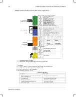
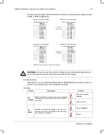
You can wire the digital input terminals for internal or external power supply in either
a PNP or NPN configuration.
WARNING!
Do not connect the +24 V AC cable to the control board ground when
the control board is powered using an external 24 V AC supply.
Communications
Terminals 29
…
31 provide Embedded fieldbus, EFB (EIA-485) connections used to
control or monitor the drive from a fieldbus controller.
Switches
Switch
Description
Position
S4
(TERM)
EFB link termination. Must be set to the terminated
(ON) position when the drive is the first or last unit
on the link.
Bus not terminated
(
default
)
Bus terminated
S5
(BIAS)
Switches on the biasing voltages to the bus. One
(and only one) device, preferably at the end of the
bus must have the bias on.
Bias off (
default
)
Bias on
PNP connection (source)
X2 & X3
10 +24V
11 DGND
12 DCOM
13 DI1
14 DI2
15 DI3
16 DI4
17 DI5
18 DI6
PNP connection (source)
X2 & X3
10 +24V
11 DGND
12 DCOM
13 DI1
14 DI2
15 DI3
16 DI4
17 DI5
18 DI6
+24
V
DC
0
V
DC
In24
V power supply
Ex24
V power supply
In24
V power supply
Ex24
V power supply
X2 & X3
10 +24V
11 DGND
12 DCOM
13 DI1
14 DI2
15 DI3
16 DI4
17 DI5
18 DI6
NPN connection (sink)
NPN connection (sink)
X2 & X3
10 +24V
11 DGND
12 DCOM
13 DI1
14 DI2
15 DI3
16 DI4
17 DI5
18 DI6
0
V
DC
+24
V
DC
Note:
DI6 is not supported in the NPN configuration.
TERM
ON
TERM
ON
BIAS
ON
BIAS
ON
ACH580_Inst_Op_Maint_Rev G.book Page 43

