The cable sizing is based on max. 9 cables laid on a cable ladder side by side, three ladder type trays
one on top of the other, ambient temperature 30 °C PVC insulation, surface temperature 70 °C (EN
60204-1 and IEC 60364-5-52). For other conditions, dimension the cables according to local safety reg-
ulations, appropriate input voltage and the load current of the drive.
1)
The cable sizing is based on NEC Table 310-16 for copper wires, 75 °C wire insulation at 40 °C ambient
temperature. Not more than three current-carrying conductors in raceway or cable or earth (directly buried).
For other conditions, size the cables according to local safety regulations, appropriate input voltage and
the load current of the drive.
2)
Terminal data for the control cables
See chapter
Electrical power network specification
ACH580-04-xxxx-4 drive modules: 380...480 V AC 3-phase ±10%. This is indicated
in the type designation label as typical input voltage levels 3~400/480 V AC.
Voltage (U
1
)
TN (grounded) and IT (ungrounded) systems
Network type
Maximum allowable prospective short-circuit current is 65 kA when protected by
the fuses given in the fuse table.
Rated conditional short-
circuit current I
cc
(IEC 61439-1)
Maximum allowable prospective short-circuit current is 65 kA when protected by
the fuses given in the fuse table.
Prospective short-circuit
current rating Pscc
(IEC 61800-5-1)
The drive is suitable for use on a circuit capable of delivering not more than
100,000 rms symmetrical amperes at 480 V maximum when protected by the fuses
given in the fuse table.
Prospective short-circuit
current rating SCCR
(UL 61800-5-1)
48 to 63 Hz, maximum rate of change 17%/s
Frequency
Max. ± 3% of nominal phase to phase input voltage
Imbalance
0.98 (at nominal load)
Fundamental power
factor (cos phi
1
)
Motor connection data
Asynchronous AC induction motors, synchronous reluctance motors and synchron-
ous permanent magnet motors
Motor types
0 to
U
1
, 3-phase symmetrical. This is indicated in the type designation label as
typical output voltage level as 3~0…
U
1
.
Voltage (U
2
)
0…500 Hz. For drives with du/dt filter: 200 Hz
Frequency
0.01 Hz
Frequency resolution
See section
Current
1 kHz, 2 kHz, 4 kHz, 8 kHz (depends on the parameter settings). See the firmware
manual.
Switching frequency
146 Technical data
Summary of Contents for ACH580-04
Page 1: ... ABB DRIVES FOR HVAC ACH580 04 drive modules Hardware manual ...
Page 2: ......
Page 4: ......
Page 54: ...54 ...
Page 88: ...88 ...
Page 100: ...100 ...
Page 118: ...118 ...
Page 122: ...122 ...
Page 124: ...124 ...
Page 128: ...3 6 5 5 128 Maintenance ...
Page 134: ...134 ...
Page 156: ...R10 standard configuration 156 Dimension drawings ...
Page 157: ...R10 with E208 0H354 H356 H370 0H371 Dimension drawings 157 ...
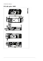
Page 158: ...R10 with option B051 158 Dimension drawings ...
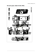
Page 159: ...R10 with option E208 H356 P906 192 Tools R10 3 1 Dimension drawings 159 ...
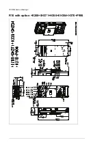
Page 160: ...R10 with option E208 0H371 H356 0H354 H370 P906 Tools 191 R10 2 1 160 Dimension drawings ...
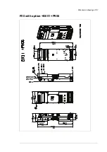
Page 161: ...R10 with option B051 P906 190 Tools R10 1 1 Dimension drawings 161 ...
Page 162: ...R11 standard configuration 162 Dimension drawings ...
Page 163: ...R11 with option E208 0H371 H356 0H354 H370 Dimension drawings 163 ...
Page 164: ...R11 with option B051 164 Dimension drawings ...
Page 165: ...R11 with option E208 H356 P906 Dimension drawings 165 ...
Page 166: ...R11 with option E208 0H371 H356 0H354 H370 P906 166 Dimension drawings ...
Page 167: ...R11 with option B051 P906 Dimension drawings 167 ...
Page 186: ... Declaration of conformity 186 The Safe torque off function ...
Page 206: ...Dimension drawing 206 External control unit option P906 ...
Page 212: ...212 ...
Page 224: ...224 ...
Page 226: ...226 ...
Page 234: ...234 ...


