Drive module
B
CCU-24 control unit
A
1 × pair of optical cables for all major converter
power stack communication.
3
1 × 24 V power supply cable (with a ground con-
nection)
1
CAT 5e cable, must be ordered separately
4
2 × Safe Torque Off (STO) cables
2
The connectors at the drive module end are located behind the middle front cover.
M4×8 Torx T20
2 N·m (18 lbf·in)
BPOW
BGDR
SOIA
Unpacking the delivery
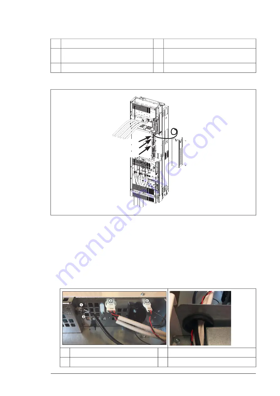
The external control unit is in a separate box inside the main drive module box.
The control cables that will connect the external control unit to the drive module are connected
to the drive module for safe transit. ABB recommends that you disconnect them before you
install the drive module:
1.
Remove the middle front cover of the drive module.
2.
Disconnect the cables. Then, carefully pull them out via the rubber grommet. Wind the
cables carefully into the plastic bag supplied, ready for installation later.
)
g
BPOW
3
V20
1
BGDR
4
V10
2
External control unit (P906) 197
Summary of Contents for ACH580-04
Page 1: ... ABB DRIVES FOR HVAC ACH580 04 drive modules Hardware manual ...
Page 2: ......
Page 4: ......
Page 54: ...54 ...
Page 88: ...88 ...
Page 100: ...100 ...
Page 118: ...118 ...
Page 122: ...122 ...
Page 124: ...124 ...
Page 128: ...3 6 5 5 128 Maintenance ...
Page 134: ...134 ...
Page 156: ...R10 standard configuration 156 Dimension drawings ...
Page 157: ...R10 with E208 0H354 H356 H370 0H371 Dimension drawings 157 ...
Page 158: ...R10 with option B051 158 Dimension drawings ...
Page 159: ...R10 with option E208 H356 P906 192 Tools R10 3 1 Dimension drawings 159 ...
Page 160: ...R10 with option E208 0H371 H356 0H354 H370 P906 Tools 191 R10 2 1 160 Dimension drawings ...
Page 161: ...R10 with option B051 P906 190 Tools R10 1 1 Dimension drawings 161 ...
Page 162: ...R11 standard configuration 162 Dimension drawings ...
Page 163: ...R11 with option E208 0H371 H356 0H354 H370 Dimension drawings 163 ...
Page 164: ...R11 with option B051 164 Dimension drawings ...
Page 165: ...R11 with option E208 H356 P906 Dimension drawings 165 ...
Page 166: ...R11 with option E208 0H371 H356 0H354 H370 P906 166 Dimension drawings ...
Page 167: ...R11 with option B051 P906 Dimension drawings 167 ...
Page 186: ... Declaration of conformity 186 The Safe torque off function ...
Page 206: ...Dimension drawing 206 External control unit option P906 ...
Page 212: ...212 ...
Page 224: ...224 ...
Page 226: ...226 ...
Page 234: ...234 ...


