Connecting EMC filter and
ground-to-phase varistor – North
America
Contents of this chapter
This chapter describes when and how to Connect the EMC filter and ground-to-phase
varistor. It gives guidelines for identifying power system types.
Identifying the grounding system of the electrical power
network
WARNING!
Only a qualified electrical professional may do the work instructed in this section.
Depending on the installation site, the work may even be categorized as live
working. Continue only if you are an electrical professional certified for the work.
Obey the local regulations. If you ignore them, injury or death can occur.
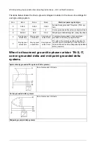
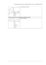
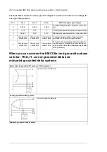
To identify the grounding system, examine the supply transformer connection. See the
applicable electrical diagrams of the building. If that is not possible, measure these voltages
at the distribution board, and use the table to define the grounding system type.
1.
input voltage line to line (U
L-L
)
2.
input voltage line 1 to ground (U
L1-G
)
3.
input voltage line 2 to ground (U
L2-G
)
4.
input voltage line 3 to ground (U
L3-G
).
26
Connecting EMC filter and ground-to-phase varistor – North America 231
Summary of Contents for ACH580-04
Page 1: ... ABB DRIVES FOR HVAC ACH580 04 drive modules Hardware manual ...
Page 2: ......
Page 4: ......
Page 54: ...54 ...
Page 88: ...88 ...
Page 100: ...100 ...
Page 118: ...118 ...
Page 122: ...122 ...
Page 124: ...124 ...
Page 128: ...3 6 5 5 128 Maintenance ...
Page 134: ...134 ...
Page 156: ...R10 standard configuration 156 Dimension drawings ...
Page 157: ...R10 with E208 0H354 H356 H370 0H371 Dimension drawings 157 ...
Page 158: ...R10 with option B051 158 Dimension drawings ...
Page 159: ...R10 with option E208 H356 P906 192 Tools R10 3 1 Dimension drawings 159 ...
Page 160: ...R10 with option E208 0H371 H356 0H354 H370 P906 Tools 191 R10 2 1 160 Dimension drawings ...
Page 161: ...R10 with option B051 P906 190 Tools R10 1 1 Dimension drawings 161 ...
Page 162: ...R11 standard configuration 162 Dimension drawings ...
Page 163: ...R11 with option E208 0H371 H356 0H354 H370 Dimension drawings 163 ...
Page 164: ...R11 with option B051 164 Dimension drawings ...
Page 165: ...R11 with option E208 H356 P906 Dimension drawings 165 ...
Page 166: ...R11 with option E208 0H371 H356 0H354 H370 P906 166 Dimension drawings ...
Page 167: ...R11 with option B051 P906 Dimension drawings 167 ...
Page 186: ... Declaration of conformity 186 The Safe torque off function ...
Page 206: ...Dimension drawing 206 External control unit option P906 ...
Page 212: ...212 ...
Page 224: ...224 ...
Page 226: ...226 ...
Page 234: ...234 ...


