background image

Description

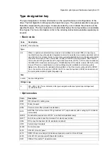
Code

FLON-01 LonWorks

®

adapter module

K452

FPBA-01 PROFIBUS DP adapter module

K454

FCAN-01 CANopen adapter module

K457

FSCA-01 RS-485 (Modbus/RTU) adapter module

K458

FCNA-01 ControlNet™ adapter module

K462

FBIP-01 BACnet/IP adapter module, 2-port

K465

FECA-01 EtherCat adapter module

K469

FEPL-02 EtherPOWERLINK adapter module

K470

FENA-21 Ethernet adapter module for EtherNet/IP™, Modbus TCP and PROFINET IO protocols,
2-port

K475

FEIP-21 EtherNet/IP adapter module

K490

FMBT-21 Modbus/TCP adapter module

K491

FPNO-21 PROFINET IO adapter module

K492

CMOD-01 External 24 V AC/DC and digital I/O extension (2×RO and 1×DO)

L501

CHDI-01 115/230 V digital input module (six digital inputs and two relay outputs)

L512

CMOD-02 External 24 V and isolated PTC interface

L523

CPTC-02 ATEX-certified thermistor protection module

L537

No extraction/installation ramp

0P919

External control unit (outside the drive module)

P906

Extended warranty 36 months from delivery

P931

Extended warranty 60 months from delivery

P932

ATEX-certified safe disconnection function

Q971

English

R700

German

R701

Italian

R702

French

R707

Spanish

R708

Portuguese

R709

Russian

R711

Chinese

R712

Turkish

R714

3AXD10000580721

Ordering codes

You can order

IP20 shrouds for frame R10 with code 3AXD50000024563 and for R11 with
3AXD50000024564

DPMP-05 control panel mounting platform with code 3AXD50000240319

DPMP-07-H control panel mounting platform with code 3AXD500003710 (US market
only).

36 Operation principle and hardware description

Summary of Contents for ACH580-04

Page 1: ... ABB DRIVES FOR HVAC ACH580 04 drive modules Hardware manual ...

Page 2: ......

Page 3: ...ACH580 04 drive modules Hardware manual Table of contents 1 Safety instructions 6 Mechanical installation 8 Electrical installation 12 Start up 3AXD50000048685 Rev B EN EFFECTIVE 2020 08 10 ...

Page 4: ......

Page 5: ...3 Applicability 23 Target audience 23 Purpose of the manual 23 Categorization by frame size and option code 24 Terms and abbreviations 25 Quick installation commissioning and operating flowchart 26 Related documents 3 Operation principle and hardware description 27 Contents of this chapter 28 Product overview 29 Layout 29 Standard drive module configuration 30 Drive module configuration with optio...

Page 6: ...iguration 52 Drive module with option B051 53 Other installation positions than vertical 53 Free space requirements 53 Free space at the top of the drive module 53 Free space around the drive module 6 Mechanical installation 55 Contents of this chapter 55 Examining the installation site 56 Moving and unpacking the unit 60 Lifting the drive module 60 Examining the delivery 60 Installation alternati...

Page 7: ...America 75 Metal conduit 75 Power cable shield 75 Selecting the control cables 75 Shielding 76 Signals in separate cables 76 Signals that can be run in the same cable 76 Relay cable 76 Control panel to drive cable 76 PC tool cable 76 Routing the cables 76 General guidelines IEC 77 General guidelines North America 78 Continuous motor cable shield conduit or enclosure for equipment on the motor cabl...

Page 8: ... of the brake resistor circuit 91 Grounding system compatibility check IEC not North America 91 EMC filter compatibility 91 Ground to phase varistor compatibility 92 Grounding system compatibility check North America 92 EMC filter compatibility 92 Ground to phase varistor compatibility 93 Connecting the power cables 93 Power cable connection diagram 94 Preparing the cable ends Symmetrical shielded...

Page 9: ...as Pt100 Pt1000 Ni1000 KTY83 and KTY84 sensor inputs X1 113 Safe torque off X4 114 Technical data 11 Installation checklist 119 Contents of this chapter 119 Checklist 12 Start up 121 Contents of this chapter 121 Start up procedure 13 Fault tracing 123 Contents of this chapter 123 LEDs 123 Warning and fault messages 14 Maintenance 125 Contents of this chapter 125 Maintenance intervals 126 Cabinet 1...

Page 10: ... 147 Brake resistor connection data 147 DC connection data 147 Control panel type 147 Control unit data 147 Efficiency 147 Protection classes 148 Ambient conditions 148 Materials 149 Applicable standards 149 Markings 150 EMC compliance IEC EN 61800 3 2004 A2012 150 Definitions 151 Category C3 152 Category C4 152 Compliance with the European Machinery Directive 153 UL and CSA checklist 153 Design l...

Page 11: ...ly 175 Multiple ACH580 04 drives internal power supply 176 Multiple ACH580 04 drives external power supply 176 Activation switch 177 Cable types and lengths 177 Grounding of protective shields 178 Operation principle 179 Start up including acceptance test 179 Competence 179 Acceptance test reports 179 Acceptance test procedure 181 Use 182 Maintenance 182 Competence 183 Fault tracing 184 Safety dat...

Page 12: ...ables 197 Unpacking the delivery 198 Installing the control unit 198 Installation procedure 198 Optical components 203 Connecting the control unit to the drive module 205 Maintenance 206 Dimension drawing 21 CHDI 01 115 230 V digital input extension module 207 Contents of this chapter 207 Product overview 208 Layout and connection examples 209 Mechanical installation 209 Necessary tools 209 Unpack...

Page 13: ...Installing the module 221 Electrical installation 221 Necessary tools and instructions 221 Wiring 221 Start up 221 Setting the parameters 222 Diagnostics 222 Faults and warning messages 222 LEDs 222 Technical data 223 Dimension drawing 24 Filters 225 Contents of this chapter 225 When is a du dt filter necessary 225 Selection table 225 Ordering codes 225 Description installation and technical data ...

Page 14: ...connect the EMC filter and ground to phase varistor TN S IT corner grounded delta and mid point grounded delta systems 233 Connecting EMC filter North America 233 Connecting ground to phase varistor North America 27 Step by step drawings for an installation example of a drive module with the B051 option in a Rittal VX25 600 mm wide enclosure Further information 14 Table of contents ...

Page 15: ...you how to prevent the danger Notes draw attention to a particular condition or fact or give information on a subject The manual uses these warning symbols WARNING Electricity warning tells about hazards from electricity which can cause injury or death or damage to the equipment WARNING General warning tells about conditions other than those caused by electricity which can cause injury or death or...

Page 16: ...Use the designated lifting points See the dimension drawings Incorrect lifting can cause danger or damage Obey the local laws and regulations applicable to lifting such as requirements for planning the lift for capacity and condition of lifting equipment and for training of personnel Attach the drive cabinet to the floor to prevent it from toppling over The cabinet has a high center of gravity Whe...

Page 17: ...AUA0000086323 To prevent the drive module from falling attach its top lifting lugs with chains to the cabinet 1 before you push the module into the cabinet and pull it from the cabinet Push the module into the cabinet and pull it from the cabinet carefully preferably with help from another person Keep a constant pressure with one foot on the base of the module 2 to prevent the module from falling ...

Page 18: ... automatically and continue operation after a fault or supply break If these functions are activated the installation must be clearly marked as defined in IEC EN 61800 5 1 subclause 6 5 3 for example THIS MACHINE STARTS AUTOMATICALLY The maximum drive power cycles is five times in ten minutes Power cycling the drive too often can damage the charging circuit of the DC capacitors If you have connect...

Page 19: ...es to let the intermediate circuit capacitors discharge before you continue 3 Protect any other energized parts in the work location against contact 4 Take special precautions when close to bare conductors 5 Measure that the installation is de energized If the measurement requires removal or disassembly of shrouding or other cabinet structures obey the local laws and regulations applicable to live...

Page 20: ...e chopper and resistor are in use they are at a dangerous voltage Option D150 External wiring can supply dangerous voltages to the relay outputs of the control units of the drive The Safe torque off function does not remove the voltage from the main and auxiliary circuits The function is not effective against deliberate sabotage or misuse Optical components WARNING Obey these instructions If you i...

Page 21: ...the equipment can occur Keep the cabinet doors closed when the drive is powered With the doors open a risk of a potentially fatal electric shock arc flash or high energy arc blast exists If you have a cardiac pacemaker or other electronic medical device keep away from the area near motor drive and the drive power cabling when the drive is in operation There are electromagnetic fields present which...

Page 22: ...e with a safety switch or by other means If you cannot disconnect the motor make sure that the motor cannot rotate during work Make sure that no other system like hydraulic crawling drives can rotate the motor directly or through any mechanical connection like felt nip rope etc Do the steps in section Electrical safety precautions page 18 Install temporary grounding to the drive output terminals T...

Page 23: ... do maintenance work on the drive or create instructions for the end user of the drive concerning the installation and maintenance of the drive Read the manual before working on the drive You are expected to know the fundamentals of electricity wiring electrical components and electrical schematic symbols Purpose of the manual This manual provides information needed for planning the installation i...

Page 24: ... 21 Optional CANopen adapter module FCAN Optional ControlNet adapter module FCNA 01 Optional DeviceNet adapter module FDNA 01 Optional EtherCAT adapter module FECA 01 Optional Ethernet adapter module FEIP 21 Optional Ethernet adapter module for EtherNet IP Modbus TCP and PROFINET IO protocols 2 port FENA 21 Optional Ethernet POWERLINK adapter module FEPL 02 Optional LonWorks adapter module FLON 01...

Page 25: ...asuring the insulation of the input power cable page 90 Measure the insulation of the input cable the motor and the motor cable and brake assembly if present Measuring the insulation of the motor and motor cable page 90 Measuring the insulation of the brake resistor cir cuit page 90 Mechanical installation page 55 Install the additional components into the cabinet eg main disconnector main contact...

Page 26: ...form for control panels installation guide 3AXD50000308484 DPMP 04 05 mounting platform for control panels installation guide 3AXD50000167555 External control unit P906 for ACH580 04 ACQ580 04 and ACS580 04 drives supplement 3AFE68573360 FDNA 01 DeviceNet adapter module user s manual 3AXD50000158614 FPNO 21 PROFINET adapter module user s manual 3AUA0000109533 FSCA 01 RS 485 adapter module user s m...

Page 27: ...peration principle and hardware description Contents of this chapter This chapter describes the operating principle and construction of the drive module 3 Operation principle and hardware description 27 ...

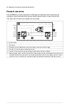
Page 28: ...ernating current and voltage to direct current and voltage 2 DC link DC circuit between rectifier and inverter 3 Inverter Converts direct current and voltage to alternating current and voltage 4 Brake chopper option D150 Conducts the surplus energy from the intermediate circuit of the drive to the brake resistor when necessary The chopper operates when the DC link voltage exceeds a certain maximum...

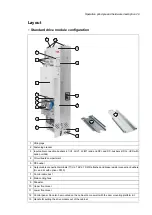
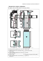
Page 29: ...rtment 4 PE busbar 5 Output cable connection terminals T1 U2 T2 V2 T3 W2 attached and brake resistor connection busbars R and R with option D150 6 Control cable duct 7 Main cooling fans 8 Pedestal 9 Upper front cover 10 Lower front cover 11 Control panel Can also be mounted on the cabinet door as well with the door mounting platform kit 12 Handle for pulling the drive module out of the cabinet 13 ...

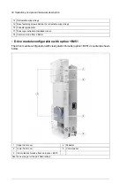
Page 30: ...er E208 18 Drive module configuration with option B051 The drive module configuration with clear plastic shrouds option B051 mounted is shown below I I r r r l 2 1 4 5 3 Pedestal 4 Upper front cover 1 Control panel 5 Lower front cover 2 Clear plastic shrouds attached option B051 3 See the next page for the part descriptions 30 Operation principle and hardware description ...

Page 31: ... Metallic shroud With option H370 the shroud includes a ground bar 10 Clear plastic shroud to be attached on top of the drive module lead through for top cabling with option B051 3 Control unit 11 Upper back clear plastic shroud with option B051 4 Pedestal guide plate 12 Lower back clear plastic shroud with option B051 5 Telescopic extraction installation ramp 13 Front clear plastic shroud with op...

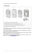
Page 32: ... mounted on the upper front cover of the drive module DPMP 03 control panel mounting platform is included in the standard delivery It allows you to mount the control panel on the cabinet door Note The standard delivery in the US market is with the external control unit option P906 and the DPMP 07 H control panel mounting platform For the use of the control panel see the firmware manual or ACx AP x...

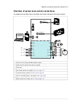
Page 33: ... 3 2 1 4 5 t R R 7 Option slot 1 for optional fieldbus adapter modules 1 Option slot 2 for optional I O extension modules 2 Panel port 3 I O terminal blocks See chapter Control unit page 107 4 Control panel see section Connecting a PC page 97 5 du dt or sine filter optional see chapter Filters page 225 6 Brake resistor See chapter Resistor braking page 187 7 Operation principle and hardware descri...

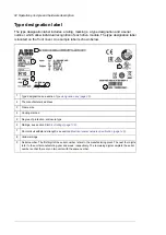
Page 34: ...turer s address 2 Frame size 3 Cooling method 4 Degree of protection enclosure type 5 Ratings see section Electrical ratings page 136 6 Short circuit withstand strength see section Electrical power network specification page 146 7 Valid markings 8 Serial number The first digit of the serial number refers to the manufacturing plant The next four digits refer to the unit s manufacturing year and wee...

Page 35: ...Modbus RTU adapter module CEIA 01 Safe torque off function coated boards printed multilingual quick installation and start up guides 04 Note In the US market the standard offering differs in that the door mounting kit is the DPMP 06 H the control unit is external P906 the DC connection busbars H356 are included and the quick guide contains English language only Size See the ratings table xxxxA Vol...

Page 36: ...gital input module six digital inputs and two relay outputs L512 CMOD 02 External 24 V and isolated PTC interface L523 CPTC 02 ATEX certified thermistor protection module L537 No extraction installation ramp 0P919 External control unit outside the drive module P906 Extended warranty 36 months from delivery P931 Extended warranty 60 months from delivery P932 ATEX certified safe disconnection functi...

Page 37: ...Basic requirements for the cabinet construction are listed below Make sure that the cabinet frame is sturdy enough to carry the weight of the components control circuitry and other equipment installed in it the cabinet protects the modules against contact and agrees with the requirements for dust and humidity the cabinet frame and doors are strong enough to provide adequate protection against flam...

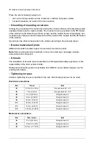
Page 38: ...xide layer and apply suitable anti oxidant joint compound Shrouds The installation of shrouds touch protection to fulfill applicable safety regulations is the responsibility of the drive system builder Ready made shrouding parts are available from ABB for some cabinet designs see the ordering information Tightening torques Unless a tightening torque is specified in the text the following torques c...

Page 39: ...chnical data leave enough free space around the components to ensure sufficient cooling Observe the minimum clearances given for each component see the technical data Air inlets and outlets Equip the air inlets and outlets with gratings that are large enough to allow sufficient air flow in and out of the cabinet critical for correct cooling of the module guide the air flow protect against contact ...

Page 40: ...nal equipment must also be ventilated The internal cooling fans of the converter modules and filters are usually sufficient to keep the component temperatures low enough in IP20 UL Type 1 and IP42 UL Type 1 filtered cabinets Additional fans are present in the example designs as needed If you install additional heat generating components to the cabinet make sure to upgrade the cooling system accord...

Page 41: ...better the interference attenuation The maximum recommended diameter of a hole in galvanic metal contact in the covering cabinet structure is 100 mm 3 94 in Pay special attention to the cooling air inlet and outlet gratings The best galvanic connection between the steel panels is achieved by welding them together as no holes are necessary If welding is not possible ABB recommends to leave the seam...

Page 42: ...ABB recommends 360 high frequency grounding of the motor cable shields at their entries The grounding can be implemented by a knitted wire mesh screening as shown below 3 1 6 4 5 2 Cable 1 Cable tie 2 Strain relief 3 Bare cable shield 4 Knitted wire mesh 5 Cabinet entry plate 6 ABB recommends 360 high frequency grounding of the control cable shields at their entries The shields can be grounded by ...

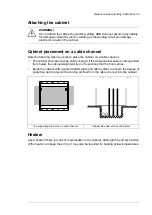
Page 43: ...t base is not supported from below the cabinet weight will lie on the sections that the floor carries Equip the cabinet with a sealed bottom plate and cable entries to ensure the degree of protection and to prevent the cooling air flow from the cable channel into the cabinet Cabinet side view with a bottom plate The supporting structure on a cable channel Heaters Use a heater if there is a risk of...

Page 44: ... guide 3AXD50000308484 DPMP 04 and DPMP 05 mounting platform for control panels installation guide 3AXD50000289561 DPMP 06 07 mounting platform for control panels installation guide DPMP 05 DPMP 03 DPMP 01 IP66 inside and outside the cabinet door IP65 UL Type 12 when control panel is mounted IP54 UL Type 12 when control panel is mounted IP20 UL Type Open when control panel is not mounted IP20 UL T...

Page 45: ...et The chapter gives cabinet layout examples and free space requirements around the module for cooling These guidelines are essential for the safe and trouble free use of the drive system Installation positions of the drive module You can install the drive module in the bookshelf or flat position or on its back in a cabinet 5 Guidelines for planning the mechanical installation 45 ...

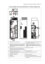
Page 46: ...quipment 2b Air outlet for the drive module and other equipment on the cabinet roof An exhaust fan if needed ABB recommends this alternative instead of 2a 2c Drive control panel with DPMP 03 mounting platform The control panel is connected to the drive module control unit inside the cabinet 3 Contactor control switch and emergency stop switch connected to the contactor control circuit inside the c...

Page 47: ...with leak proof cable entries The air baffles sep arate the cool and hot areas and prevent recircu lation of hot air 2 External control cables 10 Optional air baffle that is needed when there is no fan on the lower part of the cabinet door 1b in section Layout example door closed page 46 2e Grounding screws 11 Cabinet grounding busbar PE 3 Alternative to grounding screws 11 12 Input power cable in...

Page 48: ...Note 1 The power cable shields can also be grounded to the drive module grounding terminals Note 2 See also section Free space requirements page 53 48 Guidelines for planning the mechanical installation ...

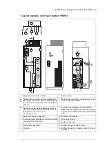
Page 49: ...ule control unit P906 Note With the integrated control unit the upper door air inlet is critical for the cooling of the control unit 9 Optional air baffle that is needed when there is no fan on the lower part of the cabinet door 1b in section Layout example door closed page 46 2c External control cables 10 Cabinet grounding busbar PE 3 Grounding screws 11 Input power cable including the protective...

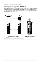
Page 50: ...he outlet is at the top either on the upper part of the door or on the roof ABB recommends that the air outlet is on the cabinet roof Use an extra exhaust fan if the air outlet is on the cabinet door 1 2 Air flow inside the drive module Air inlets and outlets of the cabinet air inlet 1 air outlet 2 50 Guidelines for planning the mechanical installation ...

Page 51: ...2d 2b 2b 1b 8 7 Drive module 3 Air flow to the drive module max 40 C 104 F 1a Disconnector and fuses 4 Air inlet to the drive module circuit boards and DC output busbars 1b Contactor 5 Vertical air baffle that separates the cool and hot areas in the cabinet 2a External drive module control unit P906 6 Vertical air baffle 2b Air flow out 7 Upper horizontal air baffle For vertical location see page ...

Page 52: ... max 40 C 104 F 1a Contactor 5 Air inlet to the drive module circuit boards and DC output busbars 1b External drive module control unit P906 6 Vertical air baffle that separates the cool and hot areas in the cabinet 2a Air flow out 7 Horizontal air baffle see Air baffles for the drive module with option B051 page 168 2b Cabinet grounding busbar 8 Optional air baffle that is needed when there is no...

Page 53: ...pace requirement at the top of the module is shown below Air outlet in the upper part of the cabinet door Air outlet on the cabinet roof 290 mm 11 42 in 1 1 2 270 mm 10 63 in 1 1 2 Air inlet 1 Air outlet 2 Free space around the drive module 20 mm 0 79 in free space around the drive module is required from the cabinet back panel and front door No free space for cooling is required on the left and r...

Page 54: ...54 ...

Page 55: ...xamining the installation site The material below the drive must be non flammable and strong enough to carry the weight of the drive See section Ambient conditions page 148 for the allowed ambient conditions and section Losses cooling data and noise page 144 for the required cooling air 6 Mechanical installation 55 10 ...

Page 56: ...g each leg a little down 1 2 and turning it aside Whenever possible attach the module also with chains Do not tilt the module It is heavy and its center of gravity is high The module overturns from a sideways tilt of 5 degrees Do not leave the module unattended on a sloping floor 1 2 3 3AUA0000086323 Move the transport package by pallet truck to the installation site 56 Mechanical installation ...

Page 57: ...upport 3 Drive module with factory installed options and multilingual residual voltage warning sticker top guide plate pedestal guide plate telescopic ramp package fastening screws in a plastic bag control unit options delivery documents printed multilingual installation and start up quick guide Other printed manuals if ordered 4 Ramp box With option H370 also input cable connection terminals box ...

Page 58: ...09484 15 3 5 10 6 Paper fill 1 Clear plastic shroud for output cabling 2 Cardboard box cover 3 Cardboard box bottom 4 Support 5 Bands 6 Back clear plastic shroud lower 7 Back clear plastic shroud upper 8 Front clear plastic shroud 9 Clear plastic shroud for input cabling 10 Top clear plastic shroud 11 Clear plastic shroud for input cable entry from side 12 Screws in a plastic bag 13 Metallic shrou...

Page 59: ...rminal 5 Cardboard box 6 Screws and insulators in a plastic bag 7 Box B2 contains additionally this box with option H370 3AXD5000009522 3 6 4 2 5 1 7 Metallic shroud with ground bar 1 Paper fill 2 Input cable connection terminal L3 W1 3 Input cable connection terminal L2 V1 4 Input cable connection terminal L1 U1 5 Cardboard box 6 Screws and insulators in a plastic bag 7 Mechanical installation 59...

Page 60: ...ng the drive module Lift the drive module only by the lifting lugs Examining the delivery Examine that all the items are present and there are no signs of damage Read the data on the type designation label of the drive module to make sure that the module is of the correct type See section Type designation key page 35 Insert lifting hooks to the drive module lifting eyes and lift the module to the ...

Page 61: ...and output terminals with cable lugs or by busbars Drive module without pedestal option 0H354 The drive module without pedestal can be mounted on a wall or a cabinet with four screws through the mounting holes at the top and bottom of the module Make sure that the cabinet mounting plate and frame are strong enough to carry the weight of the drive module Attaching the drive module to a mounting pla...

Page 62: ...module You can ground the drive module from its top back to the cabinet frame with these alternatives 1 from the grounding hole 2 to a Rittal punched section with fastening bracket 2 1 Tapping screw M6 12 Torx T30 Hex 9 N m 62 Mechanical installation ...

Page 63: ...Installing the bottom grille for IP20 degree protection For option B051 If IP20 degree of protection is needed from the bottom side install the bottom grille as shown below Mechanical installation 63 10 ...

Page 64: ...rom the top of the drive module after the installation If the covering is not removed the cooling air cannot flow freely through the module and the drive will run to overtemperature Installing external control unit option P906 See chapter External control unit option P906 page 195 64 Mechanical installation ...

Page 65: ...ver Selecting the main supply disconnecting device You must equip the drive with a main supply disconnecting device which meets the local safety regulations You must be able to lock the disconnecting device to the open position for installation and maintenance work European Union To meet the European Union Directives according to standard EN 60204 1 Safety of Machinery the disconnecting device mus...

Page 66: ...e PC tool Make sure that the motor withstands the maximum peak voltage in the motor terminals See Requirements table page 67 For basics of protecting the motor insulation and bearings in drive systems see Protecting the motor insulation and bearings page 66 Note Consult the motor manufacturer before using a motor whose nominal voltage differs from the AC line voltage connected to the drive input T...

Page 67: ... frame size IEC 400 PN 100 kW and frame size IEC 315 PN 469 hp or frame size NEMA 580 134 hp PN 469 hp or NEMA 500 frame size NEMA 580 PN 134 hp and frame size NEMA 500 N CMF N Standard UN 500 V Random wound M2_ M3_ and M4_ N du dt CMF N du dt du dt Standard 500 V UN 600 V or N CMF N Reinforced N du dt CMF N du dt du dt Reinforced 600 V UN 690 V cable length 150 m N CMF N Reinforced 600 V UN 690 V...

Page 68: ... UN 600 V or N CMF N or CMF Reinforced ÛLL 1800 V N du dt CMF du dt N du dt Reinforced ÛLL 1800 V 600 V UN 690 V N CMF N CMF Reinforced ÛLL 2000 V 0 3 micro second rise time1 1 If the intermediate DC circuit voltage of the drive is increased from the nominal level due to long term resistor braking cycles check with the motor manufacturer if additional output filters are needed in the applied drive...

Page 69: ...earings in drive systems for ABB random wound motor series for example M3AA M3AP and M3BP Requirement for Nominal AC supply voltage ABB du dt and common mode filters insulated N end motor bearings Motor insulation system PN 200 kW 100 kW PN 200 kW PN 100 kW PN 268 hp 140 hp PN 268 hp PN 140 hp N CMF N Standard UN 500 V du dt N CMF du dt N du dt Standard 500 V UN 600 V or N CMF N Reinforced du dt N...

Page 70: ...rcuit voltage of the drive is increased from the nominal level due to long term resistor braking cycles check with the motor manufacturer if additional output filters are needed in the applied drive operation range Additional data for calculating the rise time and the peak line to line voltage The diagrams below show the relative peak line to line voltage and rate of change of voltage as a functio...

Page 71: ...rk use one of the preferred cable types See Preferred power cable types page 72 Symmetrical shielded cable reduces electromagnetic emission of the whole drive system as well as the stress on motor insulation bearing currents and wear Metal conduit reduces electromagnetic emission of the whole drive system The protective conductor must always have an adequate conductivity Unless local wiring regula...

Page 72: ...arth conductor is damaged If the protective earth conductor is separate that is it does not form part of the input power cable or the input power cable enclosure the minimum cross sectional area must be 2 5 mm2 when the conductor is mechanically protected or 4 mm2 when the conductor is not mechanically protected Typical power cable sizes See the technical data Power cable types Preferred power cab...

Page 73: ... to 30 kW 40 hp Yes EMT Four conductor cabling in metal conduit three phase conductors and PE eg EMT or four conductor ar mored cable Yes with motors up to 100 kW 135 hp A potential equalization between the frames of motor and driven equipment is required Yes Well shielded Al Cu shield or ar mor four conductor cable three phase conductors and a PE No Yes PE WARNING If you use unshielded single cor...

Page 74: ...electrical conduit Type LFMC Conduit Non metallic2 3 Prefer symmetrical shielded VFD cable Liquid tight flexible non metallic conduit Type LFNC Use separate conduit run for each motor Do not run input power wiring and motor wiring in the same conduit Wireways2 Prefer symmetrical shielded VFD cable Metallic Separate motor wiring from input power wiring and other low voltage wiring Do not run output...

Page 75: ...with a copper or aluminum shield The minimum requirement of the motor cable shield of the drive is shown below It consists of a concentric layer of copper wires with an open helix of copper tape or copper wire The better and tighter the shield the lower the emission level and bearing currents 1 3 4 5 2 Insulation jacket 1 Helix of copper tape or copper wire 2 Copper wire shield 3 Inner insulation ...

Page 76: ...ximum length of the cable is 3 m 9 8 ft Routing the cables General guidelines IEC Route the motor cable away from other cables Motor cables of several drives can be run in parallel installed next to each other Install the motor cable input power cable and control cables on separate trays Avoid long parallel runs of motor cables with other cables Where control cables must cross power cables make su...

Page 77: ...guidelines North America Make sure that the installation is in accordance with national and local codes Obey these general guidelines Use separate conduits for the input power motor brake resistor optional and control cabling Use separate conduit for each motor cabling The following figure illustrates the cable routing guidelines with an example drive Guidelines for planning the electrical install...

Page 78: ...trical shielded cable or install the cabling in a metal conduit Make sure that there is a good and continuous galvanic connection in the shield conduit between drive and motor Connect the shield conduit to the protective ground terminal of the drive and the motor Separate control cable ducts Put 24 V DC and 230 V AC 120 V AC control cables in separate ducts unless the 24 V DC cable is insulated fo...

Page 79: ...off the current when necessary Depending on a drive parameter value the function either monitors a calculated temperature value based on a motor thermal model or an actual temperature indication given by motor temperature sensors The motor thermal protection model supports thermal memory retention and speed sensitivity The user can tune the thermal model further by feeding in additional motor and ...

Page 80: ...ou in selecting the breaker type when the supply network characteristics are known WARNING Due to the inherent operating principle and construction of circuit breakers independent of the manufacturer hot ionized gases can escape from the breaker enclosure in case of a short circuit To ensure safe use pay special attention to the installation and placement of the breakers Obey the manufacturer s in...

Page 81: ...21 01 Vector start mode to Automatic in vector mode or parameter 21 19 Scalar start mode to Automatic in scalar mode to make flying start starting into a rotating motor possible If the installation is equipped with a main contactor prevent its tripping at the input power break For example use a time delay relay hold in the contactor control circuit WARNING Make sure that the flying restart of the ...

Page 82: ...ed safe motor disconnection without contactor using the drive Safe torque off function To implement the thermal protection of a motor in explosive atmosphere Ex motor you must also use an ATEX certified Ex motor order an ATEX certified thermistor protection module for the drive option L357 or acquire and install an ATEX compliant protection relay do the necessary connections For more information s...

Page 83: ...is will damage or even burn the contactor completely Implementing a bypass connection If bypassing is required employ mechanically or electrically interlocked contactors between the motor and the drive and between the motor and the power line Make sure with interlocking that the contactors cannot be closed simultaneously The installation must be clearly marked as defined in IEC EN 61800 5 1 subcla...

Page 84: ...K1 Bypass contactor K4 Drive output contactor K5 Drive main contactor on off control S11 Motor power supply selection drive or direct on line S40 Start when motor is connected direct on line S41 Stop when motor is connected direct on line S42 84 Guidelines for planning the electrical installation ...

Page 85: ...e motor power supply from direct on line to the drive with S40 3 Close the main contactor of the drive with switch S11 turn to position ST for two seconds and leave to position 1 4 Start the drive and the motor with the drive control panel start key drive in the local control mode or the external start signal drive in the remote control mode Protecting the contacts of relay outputs Inductive loads...

Page 86: ...cally do not meet these requirements As an alternative you can connect the sensor with basic insulation to the analog digital input s of the drive if you do not connect any other external control circuits to the drive digital and analog inputs 3 You can connect the sensor to the drive via an option module The sensor and the module must form a double or reinforced insulation between the motor live ...

Page 87: ...etween the sensor connector and the other connectors of the mod ule including drive control unit connector No special re quirements for the thermistor insulation level The drive control unit is PELV compatible also when the module and a thermistor pro tection circuit are installed CMOD 02 No special requirement x CPTC 02 Guidelines for planning the electrical installation 87 ...

Page 88: ...88 ...

Page 89: ...ve configuration Safety WARNING If you are not a qualified electrical professional do not do installation or maintenance work Obey the safety instructions of the drive If you ignore them injury or death or damage to the equipment can occur Grounding the motor cable shield at the motor end For minimum radio frequency interference ground the cable shield 360 degrees at the cable entry of the motor t...

Page 90: ...ce work 1 Do the steps in section Electrical safety precautions page 18 before you start the work 2 Make sure that the motor cable is disconnected from the drive output terminals 3 Measure the insulation resistance between each phase conductor and the protective earth conductor Use a measuring voltage of 1000 V DC The insulation resistance of an ABB motor must be more than 100 Mohm reference value...

Page 91: ...er E210 as standard You can install the drive with the EMC filter connected to a symmetrically grounded TN S system IT system corner grounded delta mid point grounded delta and TT system Note If you disconnect the EMC filter the electromagnetic compatibility of the drive decreases Ground to phase varistor compatibility The drive is equipped with an internal ground to phase varistor as standard You...

Page 92: ...metrically grounded TN S system IT system corner grounded delta or mid point grounded delta system you can connect the internal EMC filter See section Connecting EMC filter North America page 233 Note When the internal EMC filter is disconnected the electromagnetic compatibility of the drive is reduced Ground to phase varistor compatibility The drive is equipped with an internal ground to phase va...

Page 93: ...onductor See section General guidelines page 71 2 ABB recommends 360 degree grounding at the cabinet entry if a shielded cable is used Ground the other end of the input cable shield or PE conductor at the distribution board 3 ABB recommends 360 degree grounding at the cabinet entry 4 Use a separate grounding cable if the conductivity of the shield does not meet the requirements of IEC 61800 5 1 se...

Page 94: ...a wear Preparing the cable ends Symmetrical shielded cables 1 Peel off 3 5 cm 1 1 4 2 in of the outer insulation of the cables at the cable entries with the conductive sleeves for the 360 high frequency grounding 2 Prepare the ends of the cables PE PE WARNING Apply grease to stripped aluminum conductors before attaching them to non coated aluminum cable lugs Obey the grease manufacturer s instruct...

Page 95: ...ol unit in the same way In addition connect the control unit to the drive module as instructed in chapter External control unit option P906 page 195 2 Combi screw M4 8 Torx T20 2 N m 1 5 3 1 5 lbf ft 1 Remove the middle front cover of the drive module 2 Attach the option modules if not attached already See section Installation example of drive module with IP20 shrouds option B051 page 101 3 Lead t...

Page 96: ... Connect the conductors to the appropriate detachable terminals of the control unit See chapter Control unit page 107 for the default I O connections of the drive module Use shrink tubing or insulating tape to contain any stray strands Tighten the screws to secure the connection Note Keep any signal wire pairs twisted as close to the terminals as possible Twisting the wire with its return wire red...

Page 97: ...n indication whenever the connection is active 5 See the documentation of the PC tool for setup instructions Start Stop Loc Rem Start Stop Loc Rem USB connected 3a 4 3b 2 2 Connecting a remote panel or chaining one panel to several drives You can connect a remote ACH AP H or ACH AP W control panel to the drive or to chain the control panel or a PC to several drives on a panel bus with a CDPI 01 co...

Page 98: ...ts position on the control unit 2 Tighten the mounting screw 3 Tighten the grounding screw CHASSIS to 0 8 N m 7 lbf in The screw grounds the module It is necessary for fulfilling the EMC requirements and for correct operation of the module 1 2 3 98 Electrical installation ...

Page 99: ...HASSIS to 0 8 N m 7 lbf in The screw tightens the connections and grounds the module It is necessary for fulfilling the EMC requirements and for correct operation of the module 1 2 Wiring the optional modules See the appropriate option module manual or for I O options the appropriate chapter in this manual Electrical installation 99 11 ...

Page 100: ...100 ...

Page 101: ...laced in an upright position on the cabinet bottom with its front facing the cabinet door Instructions for option H370 full size input terminals are also given Safety WARNING If you are not a qualified electrical professional do not do installation or maintenance work Obey the safety instructions of the drive If you ignore them injury or death or damage to the equipment can occur 9 Installation ex...

Page 102: ...ing flange outer mounting level for 600 mm horizontal 5 VX 8617 030 Support rails TS 4396 500 Air filter 323 mm 323 mm Remove the filter mats 4 SK 3243 200 Customer made parts not ABB or Rittal parts See sections Preventing the recirculation of hot air page 40 and Air baffles for the drive module with option B051 page 168 2 Air baffles Required tools Set of screw drivers Torx and Pozidriv Set of m...

Page 103: ...ion in a Rittal VX25 600 mm wide enclosure page 235 and the quick installation guide Install the punched section to the back of the cabinet frame Install the support rails and pedestal guide plate to the cabinet bottom frame Install the telescopic extraction installation ramp to the pedestal guide plate Option B051 Remove the sheeting from the clear plastic shrouds from both sides Option H370 Inst...

Page 104: ...ound the input cable shields if present 360 degrees at the cabinet entry 1 Connect the twisted shields of the input cables and separate ground cable if present to the cabinet grounding busbar 2 Step drill carefully sufficiently big holes to the lead through clear plastic shroud for the cables to the connected Align the holes in the vertical direction according to the alignment holes in the shroud ...

Page 105: ...the cardboard protective covering from the drive module air outlet 12 Install the side and top clear plastic shrouds to the drive module 13 Installing the roof and door Rittal parts Install the air inlet gratings to the cabinet door and the spacers on top of the cabinet as shown below This layout has been tested by ABB Rittal 7967 000 3AUA0000145776 2 1 592 23 31 1978 77 85 Rittal 3243 200 Door 1 ...

Page 106: ...les to the top clear plastic shroud Attaching the drive module to a mounting plate Use the assembly support if you attach the drive module directly to the cabinet back plate The support prevents the drive module screws from chafing the plate M4 12 Torx 106 Installation example of drive module with IP20 shrouds option B051 ...

Page 107: ...Control unit Contents of this chapter This chapter contains the default I O connection diagram descriptions of the terminals and technical data for the drive control unit CCU 24 10 Control unit 107 ...

Page 108: ...12 DIGITAL IN Digital inputs 13 18 STO Safe torque off connection 34 38 Internal air temperature NTC sensor connection AIR IN TEMP Internal fan 2 connection FAN2 Internal fan 1 connection FAN1 Panel port control panel connec tion wired at the factory to the control panel X12 Reserved to internal use X15 EFB EIA RS 485 fieldbus connector Bias resistor switch BIAS End termination switch TERM Connect...

Page 109: ...peed selection3 17 DI5 18 Not configured DI6 Start interlock 1 1 allow start Not configured 19 RO1C X6 X7 X8 Relay outputs 20 RO1A 21 RO1B 22 Damper control 250 V AC 30 V DC 2 A RO2C 23 RO2A 24 RO2B 25 Running 250 V AC 30 V DC 2 A RO3C 26 RO3A 27 X5 RO3B Fault 1 250 V AC 30 V DC 2 A 29 B Embedded fieldbus 30 A 31 DGND S4 Embedded fieldbus EFB EIA 485 TERM S5 BIAS Termination switch X4 34 Safe torq...

Page 110: ...th jumpers at the factory 4 Use shielded twisted pair cables for digital signals 5 Ground the outer shield of the cables 360 degrees at the cabinet entry 6 WARNING Connect external AC power supply 24 V AC to control unit connectors 40 and 41 If you connect it to connector AGND DGND or SGND the power supply or the control unit can get damaged 7 Switches Position Description Switch Bus not terminate...

Page 111: ...tion are shown in the figure below External 24 V power supply Internal 24 V power supply NPN connection sink NPN connection sink X2 X3 10 24V 11 DGND 12 DCOM 13 DI1 14 DI2 15 DI3 16 DI4 17 DI5 18 DI6 0 V DC 24 V DC X2 X3 10 24V 11 DGND 12 DCOM 13 DI1 14 DI2 15 DI3 16 DI4 17 DI5 18 DI6 Note DI6 is not supported in the NPN configuration WARNING Do not connect the 24 V AC cable to the control board g...

Page 112: ...the drive auxiliary voltage output is shown below The sensor is supplied through its current output and the drive feeds the supply voltage 24 V DC Thus the output signal must be 4 20 mA not 0 20 mA 4 20 mA P I AI2 AGND 24V DGND OUT DI5 as frequency input For setting the parameters for the digital frequency input see the firmware manual DI6 as PTC input If DI6 is used as a PTC input see firmware ma...

Page 113: ... to V volt in parameter group 12 Standard AI 2 Select the excitation mode in parameter group 13 Standard AO 3 WARNING As the inputs pictured above are not insulated according to IEC 60664 the connection of the motor temperature sensor requires double or reinforced insulation between motor live parts and the sensor If the assembly does not fulfill this requirement the I O board terminals must be pr...

Page 114: ...I6 and 24 V DC 1 5 kohm 1 low temperature 4 kohm 0 high temperature open circuit 0 high temperature DI6 is not a reinforced double insulated input Connecting the motor PTC sensor to this input requires usage of a reinforced double insulated PTC sensor inside the motor 250 V AC 30 V DC 2 A Terminal size 0 14 2 5 mm2 Relay outputs RO1 RO3 Term 19 27 See section Isolation areas page 116 Current volta...

Page 115: ... Shielded twisted pair cable with twisted pair for data and a wire or pair for signal ground nominal impedance 100 165 ohms for example Belden 9842 Transmission rate 9 6 115 2 kbit s Termination by switch Embedded fieldbus X5 EIA 485 male RJ 45 connector max cable length 100 m 328 ft Control panel drive connection USB Type Mini B max cable length 2 m 7 ft Control panel PC connection Control unit 1...

Page 116: ...EN 61800 5 1 2007 Functional insulation IEC EN 61800 5 1 2007 The terminals on the control board fulfill the Protective Extra Low Voltage PELV requirements EN 50178 There is reinforced insulation between the user terminals which only accept ELV voltages and terminals that accept higher voltages relay outputs Note There is functional insulation also between the individual relay outputs Note There i...

Page 117: ...4V 11 DGND 12 DCOM 13 DI1 14 DI2 15 DI3 16 DI4 17 DI5 18 DI6 X6 X7 X8 19 RO1C 20 RO1A 21 RO1B 22 RO2C 23 RO2A 24 RO2B 25 RO3C 26 RO3A 27 RO3B X5 29 B 30 A 31 DGND X4 34 OUT1 35 OUT2 36 SGND 37 IN1 38 IN2 X10 40 24VAC DC in 41 24VAC DC in Slot 1 Slot 2 Jumper installed at factory Control unit 117 ...

Page 118: ...118 ...

Page 119: ...WARNING Stop the drive and do the steps in section Electrical safety precautions page 18 before you start the work Make sure that The ambient operating conditions meet the drive ambient conditions specification and enclosure rating IP code or UL enclosure type The supply voltage matches the nominal input voltage of the drive See the type designation label The insulation resistance of the input pow...

Page 120: ...torque Proper grounding has also been measured according to the regulations The motor cable is connected to the correct terminals the phase order is correct and the terminals are tightened to the correct torque The motor cable is routed away from other cables No power factor compensation capacitors are connected to the motor cable If an external brake resistor is connected to the drive There is an...

Page 121: ...are ready for start 2 Perform the start up tasks instructed by the cabinet installer of the drive module 3 Run setup of the drive control program according to the start up instructions given in the quick start up guide or firmware manual 4 For drives with option D150 see chapter Resistor braking page 187 5 For drive modules in which the Safe torque off function is in use Test and validate the oper...

Page 122: ...122 ...

Page 123: ...is lit Color LED Where Control unit is powered and 15 V is supplied to the control panel Green POWER Control panel mounting platform Drive in fault state Red FAULT Warning and fault messages See the firmware manual for the descriptions causes and remedies of the control program warning and fault messages 13 Fault tracing 123 ...

Page 124: ...124 ...

Page 125: ...ernet www abb com drivesservices For more information consult your local ABB Service representative www abb com searchchannels Maintenance tasks every year Tasks Item Connections and environment P Quality of supply voltage Spare parts I Spare parts P DC circuit capacitors reforming for spare modules and spare capacitors Inspections by user I Tightness of terminals I Dustiness corrosion and tempera...

Page 126: ...mainten ance intervals for certain components Consult your local ABB Service representative for additional mainten ance recommendations Cabinet Cleaning the interior of the cabinet WARNING Obey the safety instructions of the drive If you ignore them injury or death or damage to the equipment can occur If you are not a qualified electrical professional do not do installation or maintenance work WAR...

Page 127: ...nding wristband Using a normal vacuum cleaner creates static discharges which can damage circuit boards 1 Stop the drive and do the steps in section Electrical safety precautions page 18 before you start the work 2 Make sure that the drive is disconnected from the power line and all other precautions described under Grounding have been taken into consideration 3 Undo the attaching screws of the ha...

Page 128: ...3 6 5 5 128 Maintenance ...

Page 129: ...t board compartment cooling fans WARNING Obey the safety instructions of the drive If you ignore them injury or death or damage to the equipment can occur 1 Stop the drive and do the steps in section Electrical safety precautions page 18 before you start the work 2 Remove the drive module out of the cabinet as described in module replacement instructions 3 Undo the fastening screw of the fan enclo...

Page 130: ...escribed in module replacement instructions 3 Open the support legs of the pedestal 4 Undo the two screws that fasten the fan assembly plate 5 Tilt the fan assembly plate down 6 Disconnect the power supply wires of the fans 7 Remove the fan assembly from the drive module 8 Undo the fastening screws of the fan s and remove the fan s from the assembly plate 9 Install the new fan in reverse order to ...

Page 131: ... the support legs by pressing each leg a little down 1 2 and turning it aside Whenever possible attach the module also with chains Do not tilt the drive module It is heavy and its center of gravity is high The module overturns from a sideways tilt of 5 degrees Do not leave the module unattended on a sloping floor 1 2 3 3AUA0000086323 1 Stop the drive and do the steps in section Electrical safety p...

Page 132: ...tion installation ramp to the cabinet base with two screws 8 To prevent the drive module from falling attach its top lifting lugs with chains to the cabinet 1 before you push the module into the cabinet and pull it from the cabinet Push the module into the cabinet and pull it from the cabinet carefully preferably with help from another person Keep a constant pressure with one foot on the base of t...

Page 133: ...ailure or a fault trip If you think that any capacitors in the drive have failed contact ABB Reforming the capacitors The capacitors must be reformed if the drive has not been powered either in storage or unused for a year or more The manufacturing date is on the type designation label For information on reforming the capacitors see Capacitor reforming instructions 3BFE64059629 English in the ABB ...

Page 134: ...134 ...

Page 135: ...f this chapter This chapter contains the technical specifications of the drive for example the ratings sizes and technical requirements provisions for fulfilling the requirements for CE and other markings 15 Technical data 135 ...

Page 136: ...nal use PLd ILd Pn I2 Imax I1 hp A hp A A A Un 480 V 400 483 400 505 560 483 R10 505A 4 450 573 450 585 730 573 R10 585A 4 500 623 500 650 730 623 R10 650A 4 600 705 600 725 850 705 R11 725A 4 700 807 700 820 1020 807 R11 820A 4 700 807 700 880 1100 807 R11 880A 4 3AXD00000586715 UL NEC ratings Output ratings Max current Input current Frame size ACH580 04 Light duty use Nominal use PLd ILd Pn I2 I...

Page 137: ...ry The output load capacity I2 ILd IHd decreases in certain situations In such situations and where full motor power is required oversize the drive so that the total derated output current provides sufficient capacity to supply the required nominal voltage to run the motor Note The DriveSize dimensioning PC tool available from ABB http new abb com drives software tools drivesize is also suitable f...

Page 138: ... 1 10 000 m 1500 1000 m 0 95 Because the surrounding air temperature is below 40 the altitude derating can be reduced from 0 95 to 1 no derating is necessary for 1500 m altitude 3 Surrounding air temperature derating page 138 No derating is necessary for 35 C surrounding air temperature From the table in section IEC ratings page 136 drive type ACH580 04 820A 4 exceeds the I2 requirement of 750 A S...

Page 139: ... 9842 ft 3500 m 11429 ft 4000 m 13123 ft 1 00 0 95 0 85 0 90 0 80 Derating factor 1 00 Derating factor 0 95 Derating factor 0 90 Derating factor 0 85 Derating factor 0 80 For a more accurate derating use the DriveSize PC tool Switching frequency derating Switching frequencies other than 1 5 kHz can require output current derating If you change the minimum switching frequency with parameter 97 02 M...

Page 140: ...00 880 880A 4 Un 480 V 170M8557D 4150000 1600 170M6012 465000 800 505 505A 4 170M8557D 4150000 1600 170M6014 945000 1000 585 585A 4 170M8557D 4150000 1600 170M6014 945000 1000 650 650A 4 170M6016 1950000 1250 725 725A 4 170M6269 3900000 1600 820 820A 4 170M6269 3900000 1600 880 880A 4 3AXD00000586715 Note See also section Protecting the drive and input power cable in short circuits page 80 In mult...

Page 141: ...ith a lower current rating than specified may be used if they are of the same voltage and are UL 248 listed fast acting or high speed fuses 4 A fuse of a different class can be used at the high fault rating where the Ipeak and I2t of the new fuse is not greater than that of the specified fuse 5 Recommended drive fuses must be used to maintain drive UL listing Additional protection can be used Refe...

Page 142: ...C 61800 5 1 of the electrical power network kA 1 ABB molded case circuit breaker Tmax Frame size ACH580 04 Product ID Type Un 480 V 30 1SDA054412R1 R10 505A 4 T5H 630 PR221DS LS I In 630 3p F F 30 1SDA054412R1 R10 585A 4 T5H 630 PR221DS LS I In 630 3p F F 50 1SDA062770R1 R10 650A 4 T7H 1000 PR231 P LS I In 1000A 3p F F 50 1SDA062770R1 R11 725A 4 T7H 1000 PR231 P LS I In 1000A 3p F F 50 1SDA062770R...

Page 143: ...on P906 Weight Depth Width Height Frame size lb in in in 345 20 08 12 01 57 55 R10 429 20 08 12 01 65 43 R11 Weight of optional selections H370 0H371 H356 E208 0H354 Frame size kg kg kg kg kg 2 9 2 9 2 3 7 R10 2 9 2 9 2 3 7 R11 Weight of optional selections H370 0H371 H356 E208 0H354 Frame size lb lb lb lb lb 6 6 4 7 15 R10 6 6 4 7 15 R11 Height of drive module without pedestal option H354 mm Fram...

Page 144: ... for the power cables The maximum accepted cable size is 4 3 240 mm2 or 4 3 500 MCM Screw size for connecting busbars to the drive module input and output busbars M12 tightening torque 50 75 N m 37 55 lbf ft Drive modules without output cable connection terminals 0H371 and with a common mode filter E208 It is possible to use the maximum cable size 4 3 240 mm2 or 4 3 500 AWG only with special cable...

Page 145: ...0 V 3 3 150 3 3 95 505A 4 3 3 150 3 3 95 585A 4 3 3 185 3 3 120 650A 4 3 3 240 3 3 150 725A 4 4 3 185 3 3 185 820A 4 4 3 240 3 3 240 880A 4 3AXD00000588487 UL NEC 2 ACH580 04 Cu cable AWG kcmil per phase Un 400 V 2 500 MCM or 3 250 MCM 505A 4 2 600 MCM or 3 300 MCM 585A 4 2 700 MCM or 3 350 MCM 650A 4 3 500 MCM or 4 300 MCM 725A 4 3 600 MCM or 4 400 MCM 820A 4 3 600 MCM or 4 400 MCM 880A 4 Un 480 ...

Page 146: ...e prospective short circuit current is 65 kA when protected by the fuses given in the fuse table Rated conditional short circuit current Icc IEC 61439 1 Maximum allowable prospective short circuit current is 65 kA when protected by the fuses given in the fuse table Prospective short circuit current rating Pscc IEC 61800 5 1 The drive is suitable for use on a circuit capable of delivering not more ...

Page 147: ...Note that a sine filter optional at the drive output also causes a voltage decrease Brake resistor connection data See chapter Resistor braking page 187 DC connection data Capacitance mF I DC A ACH580 04 UN 400 V 14 640 505A 4 14 714 585A 4 14 870 650A 4 21 909 725A 4 21 1033 820A 4 21 1120 880A 4 Control panel type See section Type designation key page 35 Control unit data See chapter Control uni...

Page 148: ...21 3 3 2002 Contamination Class 2C2 Class 1C2 Class 3C2 Chemical gases Class 2S2 Class 1S3 packing must support this otherwise 1S2 Class 3S2 No conductive dust allowed Solid particles 2 Pollution degree 60 106 kPa 0 6 1 05 atmospheres 70 106 kPa 0 7 1 05 atmospheres 70 106 kPa 0 7 1 05 atmospheres Atmospheric pressure Max 3 5 mm 0 14 in 2 9 Hz max 15 m s2 49 ft s2 9 200 Hz sinus oidal Max 1 mm 0 0...

Page 149: ...wer drive systems Part 5 1 Safety requirements electrical thermal and energy IEC EN 61800 5 1 2007 Safety of machinery Electrical equipment of machines Part 1 General require ments Provisions for compliance The final assembler of the machine is responsible for installing EN 60204 1 2006 A1 2009 AC 2010 emergency stop device supply disconnecting device IP00 drive module into a cabinet Degrees of pr...

Page 150: ... be recycled KC mark Product complies with Korea s product safety requirements for electrical and electronic equipment and components that utilize power from 50 1000 V AC TÜV Safety Approved mark functional safety Product contains Safe Torque Off and possibly other optional safety functions which are certified by TÜV according to the relevant functional safety standards Applicable to drives and in...

Page 151: ...ed voltage equal to or above 1000 V or rated current equal to or above 400 A or intended for use in complex systems in the second environment Category C3 The drive complies with the standard with the following provisions 1 The drive is equipped with EMC filter E210 and common mode filter E208 2 The motor and control cables are selected as specified in the hardware manual 3 The drive is installed a...

Page 152: ...nd control cables are selected and routed according to the electrical planning guidelines of the drive The EMC recommendations are obeyed 4 The drive is installed according to its installation instructions The EMC recommendations are obeyed WARNING A drive of category C4 is not intended to be used on a low voltage public network which supplies domestic premises Radio frequency interference is expe...

Page 153: ...he UL fuses given elsewhere in this chapter The ampere rating is based on tests done according to the appropriate UL standard The cables located within the motor circuit must be rated for at least 75 C in UL compliant installations The input cable must be protected with fuses or circuit breakers These protective devices provide branch circuit protection in accordance with the national regulations ...

Page 154: ...usly ensure a secure connection between the product and Customer network or any other network as the case may be Customer shall establish and maintain any appropriate measures such as but not limited to the installation of firewalls application of authentication measures encryption of data installation of anti virus programs etc to protect the product the network its system and the interface again...

Page 155: ...Dimension drawings Contents of this chapter This chapter contains dimension drawings of the drive modules 16 Dimension drawings 155 ...

Page 156: ...R10 standard configuration 156 Dimension drawings ...

Page 157: ...R10 with E208 0H354 H356 H370 0H371 Dimension drawings 157 ...

Page 158: ...R10 with option B051 158 Dimension drawings ...

Page 159: ...R10 with option E208 H356 P906 192 Tools R10 3 1 Dimension drawings 159 ...

Page 160: ...R10 with option E208 0H371 H356 0H354 H370 P906 Tools 191 R10 2 1 160 Dimension drawings ...

Page 161: ...R10 with option B051 P906 190 Tools R10 1 1 Dimension drawings 161 ...

Page 162: ...R11 standard configuration 162 Dimension drawings ...

Page 163: ...R11 with option E208 0H371 H356 0H354 H370 Dimension drawings 163 ...

Page 164: ...R11 with option B051 164 Dimension drawings ...

Page 165: ...R11 with option E208 H356 P906 Dimension drawings 165 ...

Page 166: ...R11 with option E208 0H371 H356 0H354 H370 P906 166 Dimension drawings ...

Page 167: ...R11 with option B051 P906 Dimension drawings 167 ...

Page 168: ...B051 This drawing shows the dimensions of the hole in the air baffle around the drive module with option B051 The drawing also shows the correct vertical location area of the air baffle as measured from the top grill 15 0 6 168 Dimension drawings ...

Page 169: ... which are not included in a basic delivery plus code options other options to be acquired by the customer Example circuit diagram This diagram is an example for the main wiring of a drive cabinet Note that the diagram includes components which are not included in a basic delivery plus code options other options to be acquired by the customer 17 Example circuit diagram 169 ...

Page 170: ... panel 2 CCU control unit 3 Main contactor 4 Motor temperature supervision 5 Switch fuse disconnector 6 Common mode filter 7 du dt filter or sine filter 8 Drive module 9 Input and output signals 10 Alarm 11 Supply 12 360 degree grounding recommended 13 170 Example circuit diagram ...

Page 171: ...drive output stage A see the diagrams below thus preventing the drive from generating the torque required to rotate the motor If the motor is running when Safe torque off is activated it coasts to a stop The Safe torque off function has a redundant architecture that is both channels must be used in the safety function implementation The safety data given in this manual is calculated for redundant ...

Page 172: ...C 61511 1 2016 Adjustable speed electrical power drive systems Part 5 2 Safety require ments Functional IEC 61800 5 2 2016 EN 61800 5 2 2007 Safety of machinery Functional safety of safety related electrical elec tronic and programmable electronic control systems IEC 62061 2005 A1 2012 A2 2015 EN 62061 2005 AC 2010 A1 2013 A2 2015 Safety of machinery Safety related parts of control systems Part 1 ...

Page 173: ...04 drive internal power supply OUT1 24 V DC SGND STO UDC UDC A K 2 1 3 4 OUT2 24 V DC IN1 IN2 34 35 36 37 38 Drive 1 Control unit 2 Control logic 3 To motor 4 Activation switch K Single ACH580 04 drive external power supply OUT1 24 V DC SGND STO UDC UDC A 2 1 3 4 OUT2 24 V DC IN1 IN2 34 35 36 37 38 24 V DC K The Safe torque off function 173 ...

Page 174: ...y 24 14 23 13 Y1 A2 Y2 A1 31 32 OUT GND OUT1 34 OUT2 35 SGND 36 IN1 37 IN2 38 STO 1 K 2 Drive 1 Safety PLC 2 Safety relay K Single ACH580 04 drive external power supply 24 14 23 13 Y1 A2 Y2 A1 31 32 OUT GND K 2 24 V DC 1 OUT1 34 OUT2 35 SGND 36 IN1 37 IN2 38 STO Drive 1 Safety PLC 2 Safety relay K 174 The Safe torque off function ...

Page 175: ...r supply 34 35 36 37 38 OUT1 OUT2 SGND IN1 IN2 34 35 36 37 38 OUT1 OUT2 SGND IN1 IN2 STO K 24 V DC 24 V DC 2 1 STO 2 1 34 35 36 37 38 OUT1 OUT2 SGND IN1 IN2 STO 2 1 Drive 1 Control unit 2 Activation switch K The Safe torque off function 175 ...

Page 176: ...4 35 36 37 38 OUT1 OUT2 SGND IN1 IN2 STO 2 1 24 V DC Drive 1 Control unit 2 Activation switch K Activation switch In the wiring diagrams the activation switch has the designation K This represents a component such as a manually operated switch an emergency stop push button switch or the contacts of a safety relay or safety PLC 176 The Safe torque off function ...

Page 177: ...wer supply and first control unit Note A short circuit in the wiring between the switch and an STO terminal causes a dangerous fault Therefore it is recommended to use a safety relay including wiring diagnostics or a wiring method shield grounding channel separation which reduces or eliminates the risk caused by the short circuit Note The voltage at the STO input terminals of the drive must be at ...

Page 178: ... this occurs Note This parameter does not affect the operation of the STO function itself The STO function will operate regardless of the setting of this parameter a running drive will stop upon removal of one or both STO signals and will not start until both STO signals are restored and all faults reset Note The loss of only one STO signal always generates a fault as it is interpreted as a malfun...

Page 179: ...ance shall be logged into the logbook Acceptance test procedure After wiring the Safe torque off function validate its operation as follows Note If a CPTC 02 module is installed refer to its documentation Action WARNING Obey the safety instructions If you ignore them injury or death or damage to the equipment can occur Make sure that the drive can be run and stopped freely during start up Stop the...

Page 180: ...rcuit If the motor was running it should coast to a stop The drive generates a FA81 Safe Torque Off 1 loss fault indication see the firmware manual Give a start command to verify that the STO function blocks the drive s operation The motor should not start Close the STO circuit Reset any active faults Restart the drive and check that the motor runs normally Open the 2nd channel of the STO circuit ...

Page 181: ...e IGBT power semiconductor failure the drive can produce an alignment torque which maximally rotates the motor shaft by 180 p degrees with permanent magnet motors or 180 2p degrees with synchronous reluctance SynRM motors regardless of the activation of the Safe torque off function p denotes the number of pole pairs Notes If a running drive is stopped by using the Safe torque off function the driv...

Page 182: ...tegrity requirement for the safety function is SIL 2 HFT 1 or PL d cat 3 the proof test for the function must be performed at least every 12 months The STO function of the drive does not contain any electromechanical components In addition to proof testing it is a good practice to check the operation of the function when other maintenance procedures are carried out on the machinery Include the Saf...

Page 183: ...function is performed and the drive trips on an STO hardware failure fault An attempt to use the STO in a non redundant manner for example activating only one channel will trigger the same reaction See the firmware manual of the drive control program for the indications generated by the drive and for details on directing fault and warning indications to an output on the control unit for external d...

Page 184: ...ption that one failure occurs at one time No accumulated failures have been analyzed STO response times STO reaction time shortest detectable break 1 ms STO response time 2 ms typical 30 ms maximum Fault detection time Channels in different states for longer than 200 ms Fault reaction time Fault detection time 10 ms Indication delays STO fault indication parameter 31 22 delay 500 ms STO warning in...

Page 185: ... claimed for a safety function or subsystem IEC EN 62061 SILCL Safe torque off IEC EN 61800 5 2 STO Proof test interval T1 is a parameter used to define the probabilistic failure rate PFH or PFD for the safety function or subsystem Per forming a proof test at a maximum interval of T1 is required to keep the SIL capability valid The same interval must be followed to keep the PL capability EN ISO 13...

Page 186: ... Declaration of conformity 186 The Safe torque off function ...

Page 187: ... as add on kits The brake chopper handles the energy generated by a decelerating motor The extra energy increases the DC link voltage The chopper connects the brake resistor to the intermediate DC circuit whenever the voltage in the circuit exceeds the limit defined by the control program Energy consumption by the resistor losses lowers the voltage until the resistor can be disconnected Planning t...

Page 188: ... has not verified that the EMC requirements are fulfilled with custom brake resistors and cabling The customer must consider the EMC compliance of the complete installation Protecting the resistor cable against short circuits The input fuses of the drive will also protect the resistor cable when it is identical with the input cable Resistor thermal switch Use a resistor with a thermal switch stand...

Page 189: ...1 Calculate the maximum power generated by the motor during braking 2 Select a suitable drive brake chopper and brake resistor combination for the application from the brake ratings table below The braking power of the chopper must be greater than or equal to the maximum power generated by the motor during the braking 3 Make sure that the resistor selection is correct The energy generated by the m...

Page 190: ... of the default resistor Rmin WARNING Never use a brake resistor with a resistance smaller than Rmin This will cause overcurrent that will damage the brake chopper and the drive 2 make sure that the resistance of the custom resistor does not restrict the braking capability needed ie where Maximum power generated by the motor during braking Pmax Drive intermediate DC circuit voltage 1 35 1 2 415 V ...

Page 191: ...ate DC circuit by the chopper where Instantaneous load capacity of the custom resistor PR inst Drive intermediate DC circuit voltage 1 35 1 2 415 V DC when supply voltage is 380 to 415 V AC 1 35 1 2 500 V DC when supply voltage is 440 to 500 V AC or 1 35 1 2 690 V DC when supply voltage is 525 to 690 AC UDC Resistance of the custom resistor R Mechanical installation of resistors All brake resistor...

Page 192: ...nabe stop mode 20 12 Run enable 1 source and 95 20 HW options word 1 If the thermal switch is wired to another digital input input set the following parameters 1 Set the source of parameter 31 01 External event 1 source to point to the digital input where the thermal switch of the brake resistor is wired 2 Enable the brake chopper by parameter 43 06 Brake chopper enable If Enabled with thermal mod...

Page 193: ...A 4 3AXD00000586715 Maximum continuous braking power The braking is considered continuous if the braking time exceeds 30 seconds Pbrcont The minimum allowed resistance value of the brake resistor Rmin Resistance value for the listed resistor assembly R Short energy pulse that the resistor assembly withstands every 400 seconds ER Continuous power heat dissipation of the resistor when placed correct...

Page 194: ...1320 Ø 7 345 1270 ABB ordering code Weight Brake resistor type 68759285 25 kg 55 lb SAFUR125F500 68759340 30 kg 66 lb SAFUR200F500 Terminals and cable entry data See section Terminal and entry data for the power cables page 144 194 Resistor braking ...

Page 195: ...ing is included Product overview Option P906 allows the drive control unit to be installed separately from the main drive module for instance in a separate compartment The external control unit option makes the drive module removal easier as the customer control cabling can stay in place while the module is removed 20 External control unit option P906 195 ...

Page 196: ...ons see chapter Control unit 3 Cables These cables connect the control unit and the drive They are supplied with the module and come with plugs and sockets that allow disconnection at either end 3 m 9 8 ft BPOW 3 m 10 ft 2560 mm 8 4 ft CAT 5e ZBIB BGDR X7 STO1 X8 STO2 BPOW BGDR X3 SOIA ZINT V10 V20 A B 1 2 3 4 V1 V2 DPMP 03 X12 196 External control unit option P906 ...

Page 197: ...he delivery The external control unit is in a separate box inside the main drive module box The control cables that will connect the external control unit to the drive module are connected to the drive module for safe transit ABB recommends that you disconnect them before you install the drive module 1 Remove the middle front cover of the drive module 2 Disconnect the cables Then carefully pull th...

Page 198: ... equipment can occur Handle the fiber optic cables with care When you unplug the fiber optic cables always hold the connector not the cable itself Do not touch the ends of the fibers with bare hands as the ends are extremely sensitive to dirt Do not bend the fiber optic cables too tightly The minimum allowed bend radius is 35 mm 1 4 in 1 Remove the control unit from the anti static bag and place i...

Page 199: ...leave it outside the assembly Check that the cables are not against sharp edges or bare live parts 4 Connect the cables to their connectors on the ZBIB board Cables from drive mod ule ZBIB connectors View of ZBIB BPOW X3 1 X3 1 X3 2 X3 2 BGDR X7 STO 1 X7 STO 1 X8 STO 2 X8 STO 2 SOIA V10 black V1 gray V20 grey V2 black External control unit option P906 199 ...

Page 200: ...5 Connect the grounding wire 6 The kit includes a plate for the customer cable screens Attach the small bracket a first then the full clamp plate b a b 200 External control unit option P906 ...

Page 201: ... in the mounting plate for attaching the control unit Be careful to control the swarf from the drill 8 Lift the control unit onto the mounting screws Tighten the screws 9 Attach the optional modules External control unit option P906 201 ...

Page 202: ...frequency capacitor eg 3 3 nF 630 V The shield can also be grounded directly at both ends if they are in the same ground line with no significant voltage drop between the end points Tighten the screws to secure the connection 11 Connect the conductors to the appropriate detachable terminals of the control unit See the default I O diagram in chapter Control unit page 107 Use shrink tubing or insula...

Page 203: ...dule A view of drive module with optional clear plastic shrouds is shown below 2 Remove the cover plate from the control cable entry and put the rubber grommet in its place Put the control cables through the grommet Combi screw M4 8 Torx T20 2 N m 18 lbf in 1 2 2 External control unit option P906 203 ...

Page 204: ...ke sure that that cables are not against sharp edges or bare live parts ZBIB Drive module M4 8 Torx T20 2 N m 18 lbf in BPOW BGDR SOIA BPOW X3 1 X3 1 X3 2 X3 2 BGDR X7 STO1 X7 STO1 X8 STO2 X8 STO2 SOIA V1 V10 V2 V20 204 External control unit option P906 ...

Page 205: ...from the drive module in the following way 1 Remove the middle front cover of the drive module to be able to disconnect the cables 2 combi screws M4 8 T20 2 N m 18 lbf in 2 Disconnect the optical 2 STO 24 V and ground connections from the drive module and carefully remove the cables from the drive 3 Wind the cables so they will not be damaged as the drive module is removed 4 Continue the drive mod...

Page 206: ...Dimension drawing 206 External control unit option P906 ...

Page 207: ...cribes the optional CHDI 01 115 230 V digital input extension module Product overview The CHDI 01 115 230 V digital input extension module expands the inputs of the drive control unit It has six high voltage inputs and two relay outputs 21 CHDI 01 115 230 V digital input extension module 207 ...

Page 208: ...ormally open NO RO4A 52 Neutral point NEUTRAL 1 72 Common C RO5C 53 115 230 V input 3 HDI9 73 Normally closed NC RO5B 54 115 230 V input 4 HDI10 74 Normally open NO RO5A 55 Neutral point NEUTRAL 1 75 Grounding screw 3 115 230 V input 5 HDI11 76 Hole for mounting screw 4 115 230 V input 5 HDI12 77 Diagnostic LED Green The extension module is powered up 5 Neutral point NEUTRAL 1 78 1 Neutral points ...

Page 209: ...put power wait for 5 minutes after disconnecting the input power Necessary tools Screwdriver and a set of suitable bits Wiring Connect the external control cables to the applicable module terminals Ground the outer shield of the cables 360 degrees under a grounding clamp on the grounding shelf of the control cables Start up Setting the parameters 1 Power up the drive 2 If no warning is shown make ...

Page 210: ...t Installation IP20 UL Type 1 Degree of protection See the drive technical data Ambient conditions Cardboard Package Reley outputs 50 52 53 55 1 5 mm2 Maximum wire size 12 V 10 mA Minimum contact rating 250 V AC 30 V DC 2 A Maximum contact rating 1500 VA Maximum breaking capa city 115 230 V inputs 70 78 1 5 mm2 Maximum wire size 115 to 230 V AC 10 Input voltage 2 mA Maximum current leakage in digi...

Page 211: ...Dimension drawing The dimensions are in millimeters and inches CHDI 01 115 230 V digital input extension module 211 ...

Page 212: ...212 ...

Page 213: ...puts of the drive control unit It has two relay outputs and one transistor output which can function as a digital or frequency output In addition the extension module has an external power supply interface which can be used to power up the drive control unit in case the drive power supply is not on If you do not need the back up power supply you do not have to connect it because the module is powe...

Page 214: ...pen NO RO4B 52 3 pin terminal block for for transistor output 4 24 V DC 42 43 44 DO1 SRC DO1 OUT DO1 SGND 1 42 43 44 DO1 SRC DO1 OUT DO1 SGND 2 Common C RO5C 53 Source input DO1 SRC 42 Normally closed NC RO5A 54 Digital or frequency output DO1 OUT 43 Normally open NO RO5B 55 Ground earth potential DO1 SGND 44 1 Digital output connection example 2 An externally supplied frequency indicator which pr...

Page 215: ...t a qualified electrician do not do electrical work Make sure that the drive is disconnected from the input power during installation If the drive is already connected to the input power wait for 5 minutes after disconnecting the input power Necessary tools Screwdriver and a set of suitable bits Wiring Connect the external control cables to the applicable module terminals Ground the outer shield o...

Page 216: ...lay Setting Parameter Reverse 15 07 RO4 source 1 s 15 08 RO4 ON delay 1 s 15 09 RO4 OFF delay Parameter setting example for digital output This example shows how to make digital output DO1 of the extension module indicate the reverse direction of rotation of the motor with a one second delay Setting Parameter Digital output 15 22 DO1 configuration Reverse 15 23 DO1 source 1 s 15 24 DO1 ON delay 1 ...

Page 217: ...ire size 12 V 10 mA Minimum contact rating 250 V AC 30 V DC 2 A Maximum contact rating 1500 VA Maximum breaking capa city Transistor output 42 44 1 5 mm2 Maximum wire size Transistor output PNP Type 4 kohm Maximum load 30 V DC Maximum switching voltage 100 mA 30 V DC short circuit protected Maximum switching current 10 Hz 16 kHz Frequency 1 Hz Resolution 0 2 Inaccuracy External power supply 40 41 ...

Page 218: ...o drive SLOT2 1 Reinforced insulation IEC 61800 5 1 2007 Functional insulation IEC 61800 5 1 2007 Dimension drawing The dimensions are in millimeters and inches 218 CMOD 01 multifunction extension module external 24 V AC DC and digital I O ...

Page 219: ...fe torque off tripping is required the user must wire the overtemperature indication relay to the certified Safe torque off input of the drive In addition the extension module has an external power supply interface which can be used to power up the drive control unit in case the drive power supply is not on If you do not need the back up power supply you do not have to connect it because the modul...

Page 220: ...V AC DC input 24 V AC DC in 40 Normally open NO RO PTC B 63 External 24 V AC DC input 24 V AC DC in 41 Grounding screw 1 Motor thermistor connection 5 60 61 PTC IN PTC IN One to six PTC thermistors connected in series Hole for mounting screw 2 PTC connection PTC IN 60 Diagnostic LED 6 Ground earth potential PTC IN 61 Mechanical installation Necessary tools Screwdriver and a set of suitable bits 22...

Page 221: ...driver and a set of suitable bits Wiring Connect the external control cables to the applicable module terminals Ground the outer shield of the cables 360 degrees under a grounding clamp on the grounding shelf of the control cables WARNING Do not connect the 24 V AC cable to the control unit ground when the control unit is powered using an external 24 V AC supply Start up Setting the parameters 1 P...

Page 222: ...urrent 50 ohm 10 Short circuit detection The PTC input is reinforced double insulated If the motor part of the PTC sensor and wiring are reinforced double insulated voltages on the PTC wiring are within SELV limits If the motor PTC circuit is not reinforced double insulated ie it is basic insulated it is mandatory to use rein forced double insulated wiring between the motor PTC and CMOD 02 PTC ter...

Page 223: ...ve SLOT2 1 Reinforced insulation IEC 61800 5 1 2007 Functional insulation IEC 61800 5 1 2007 Dimension drawing The dimensions are in millimeters and inches CMOD 02 multifunction extension module external 24 V AC DC and isolated PTC interface 223 ...

Page 224: ...224 ...

Page 225: ...d drive page 66 Selection table The du dt filter types for the drive module types are given below du dt filter type Frame FOCH0610 70 R10 FOCH0875 70 R11 Ordering codes ABB ordering code Filter type 68550483 FOCH 0610 70 3AUA0000125245 FOCH 0875 70 Description installation and technical data of the FOCH filters See FOCH du dt filters hardware manual 3AFE68577519 English 24 Filters 225 ...

Page 226: ...226 ...

Page 227: ...zed as live working Continue only if you are an electrical professional certified for the work Obey the local regulations If you ignore them injury or death can occur To identify the grounding system examine the supply transformer connection See the applicable electrical diagrams of the building If that is not possible measure these voltages at the distribution board and use the table to define th...

Page 228: ...ying level versus time Varying level versus time X TT system the protective earth connection for the consumer is provided by a local earth elec trode and there is another independently installed at the generator Varying level versus time Varying level versus time Varying level versus time X When to disconnect ground to phase varistor TN S IT corner grounded delta and mid point grounded delta syste...

Page 229: ...Do not disconnect VAR wire PE L3 L2 L1 IT systems ungrounded or highresistance grounded 30 ohms Disconnect VAR wire L3 L2 L1 Ground to phase varistor disconnecting instructions IEC not North America 229 ...

Page 230: ...rent will cause the residual current device to trip Note ABB does not guarantee the functioning of the ground leakage detector built inside the drive In large systems the residual current device can trip without a real reason Disconnecting instruction IEC not North America Varistor VAR grounding wire is attached next to the control circuit compartment Disconnect it Insulate the end and attach it 2...

Page 231: ...tegorized as live working Continue only if you are an electrical professional certified for the work Obey the local regulations If you ignore them injury or death can occur To identify the grounding system examine the supply transformer connection See the applicable electrical diagrams of the building If that is not possible measure these voltages at the distribution board and use the table to def...

Page 232: ... level versus time Varying level versus time X TT system the protective earth connection for the consumer is provided by a local earth elec trode and there is another independently installed at the generator Varying level versus time Varying level versus time Varying level versus time X When you can connect the EMC filter and ground to phase varistor TN S IT corner grounded delta and mid point gro...

Page 233: ...tem corner grounded delta or mid point grounded delta system you can connect the internal EMC filter Contact ABB for the connection instructions Connecting ground to phase varistor North America This section is valid the UL NEC drive types The internal ground to phase varistor of the drive is disconnected as default If you install the drive to TN S system corner grounded delta or mid point grounde...

Page 234: ...234 ...
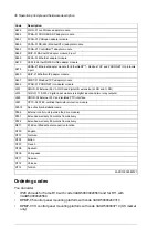
Page 235: ...n installation example of a drive module with the B051 option in a Rittal VX25 600 mm wide enclosure Step by step drawings for an installation example of a drive module with the B051 option in a Rittal VX25 600 mm wide enclosure 235 ...

Page 236: ...4 8 Torx T20 2 N m 18 lbf in Combi screw M4 8 Torx T20 2 N m 18 lbf in M6x20 Torx T25 8 N m 71 lbf in Combi screw M8 30 Hex 20 N m 14 75 lbf ft Tapping screw M6 12 Torx T30 Hex 9 N m 80 lbf in M8 Kalei nut or similar 2 pcs 236 Step by step drawings for an installation example of a drive module with the B051 option in a Rittal VX25 600 mm wide enclosure ...

Page 237: ...x T25 8 N m 71 lbf in Combi screw M12 25 Hex 70 N m 52 lbf ft Hex screw M12 35 full thread 70 N m 52 lbf ft Washer M12 or equal Hex nut M12 70 N m 52 lbf ft Washer M12 or equal Step by step drawings for an installation example of a drive module with the B051 option in a Rittal VX25 600 mm wide enclosure 237 ...

Page 238: ... 70 N m 52 lbf ft Washer M12 or equal Combi screw M6 20 Torx T25 2 N m 18 lbf in Combi screw M4 8 Torx T20 2 N m 18 lbf in Combi screw M6 20 Torx T25 2 N m 18 lbf in Combi screw M4 10 Torx T20 2 N m 18 lbf in B051 B051 B051 B051 B051 238 Step by step drawings for an installation example of a drive module with the B051 option in a Rittal VX25 600 mm wide enclosure ...

Page 239: ...ard drive module configuration Note These air baffles are compatible with option B051 only For the standard drive module configuration see section Standard drive module configuration page 29 Step by step drawings for an installation example of a drive module with the B051 option in a Rittal VX25 600 mm wide enclosure 239 ...

Page 240: ...240 Step by step drawings for an installation example of a drive module with the B051 option in a Rittal VX25 600 mm wide enclosure ...

Page 241: ... by navigating to www abb com searchchannels Product training For information on ABB product training navigate to new abb com service training Providing feedback on ABB manuals Your comments on our manuals are welcome Navigate to new abb com drives manuals feedback form Document library on the Internet You can find manuals and other product documents in PDF format on the Internet at www abb com dr...

Page 242: ...www abb com drives 3AXD50000048685B Copyright 2020 ABB All rights reserved Specifications subject to change without notice 3AXD50000048685 Rev B EN EFFECTIVE 2020 08 10 ...

Reviews: