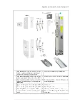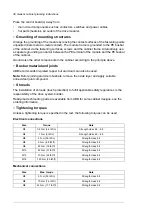
Insulation supports
Note
Max. torque
Size
Strength class 8.8
5 N·m (44 lbf·in)
M6
Strength class 8.8
9 N·m (6.6 lbf·ft)
M8
Strength class 8.8
18 N·m (13.3 lbf·ft)
M10
Strength class 8.8
31 N·m (23 lbf·ft)
M12
Cable lugs
Note
Max. torque
Size
Strength class 8.8
15 N·m (11 lbf·ft)
M8
Strength class 8.8
32 N·m (23.5 lbf·ft)
M10
Strength class 8.8
50 N·m (37 lbf·ft)
M12
Cooling and degrees of protection
■
Planning the cooling
When you plan the cooling of the cabinet:
•
make sure that the ventilation of the installation site is sufficient so that the cooling air
flow and ambient temperature requirements of the module are met (see the technical
data)
•
leave enough free space around the components to ensure sufficient cooling. Observe
the minimum clearances given for each component, see the technical data.
■
Air inlets and outlets
Equip the air inlets and outlets with gratings that:
•
are large enough to allow sufficient air flow in and out of the cabinet (critical for correct
cooling of the module)
•
guide the air flow
•
protect against contact
•
prevent water splashes from entering the cabinet
•
ensure adequate protection against flames or pressure blast originating from inside the
cabinet in case of arc flash or similar failure.
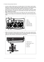
The drawing below shows two typical cabinet cooling solutions. The air inlet is at the bottom
of the cabinet. The outlet is on the roof or on the upper part of the door if room height is
limited.
Generic cabinet planning instructions 39
Summary of Contents for ACH580-04
Page 1: ... ABB DRIVES FOR HVAC ACH580 04 drive modules Hardware manual ...
Page 2: ......
Page 4: ......
Page 54: ...54 ...
Page 88: ...88 ...
Page 100: ...100 ...
Page 118: ...118 ...
Page 122: ...122 ...
Page 124: ...124 ...
Page 128: ...3 6 5 5 128 Maintenance ...
Page 134: ...134 ...
Page 156: ...R10 standard configuration 156 Dimension drawings ...
Page 157: ...R10 with E208 0H354 H356 H370 0H371 Dimension drawings 157 ...
Page 158: ...R10 with option B051 158 Dimension drawings ...
Page 159: ...R10 with option E208 H356 P906 192 Tools R10 3 1 Dimension drawings 159 ...
Page 160: ...R10 with option E208 0H371 H356 0H354 H370 P906 Tools 191 R10 2 1 160 Dimension drawings ...
Page 161: ...R10 with option B051 P906 190 Tools R10 1 1 Dimension drawings 161 ...
Page 162: ...R11 standard configuration 162 Dimension drawings ...
Page 163: ...R11 with option E208 0H371 H356 0H354 H370 Dimension drawings 163 ...
Page 164: ...R11 with option B051 164 Dimension drawings ...
Page 165: ...R11 with option E208 H356 P906 Dimension drawings 165 ...
Page 166: ...R11 with option E208 0H371 H356 0H354 H370 P906 166 Dimension drawings ...
Page 167: ...R11 with option B051 P906 Dimension drawings 167 ...
Page 186: ... Declaration of conformity 186 The Safe torque off function ...
Page 206: ...Dimension drawing 206 External control unit option P906 ...
Page 212: ...212 ...
Page 224: ...224 ...
Page 226: ...226 ...
Page 234: ...234 ...

